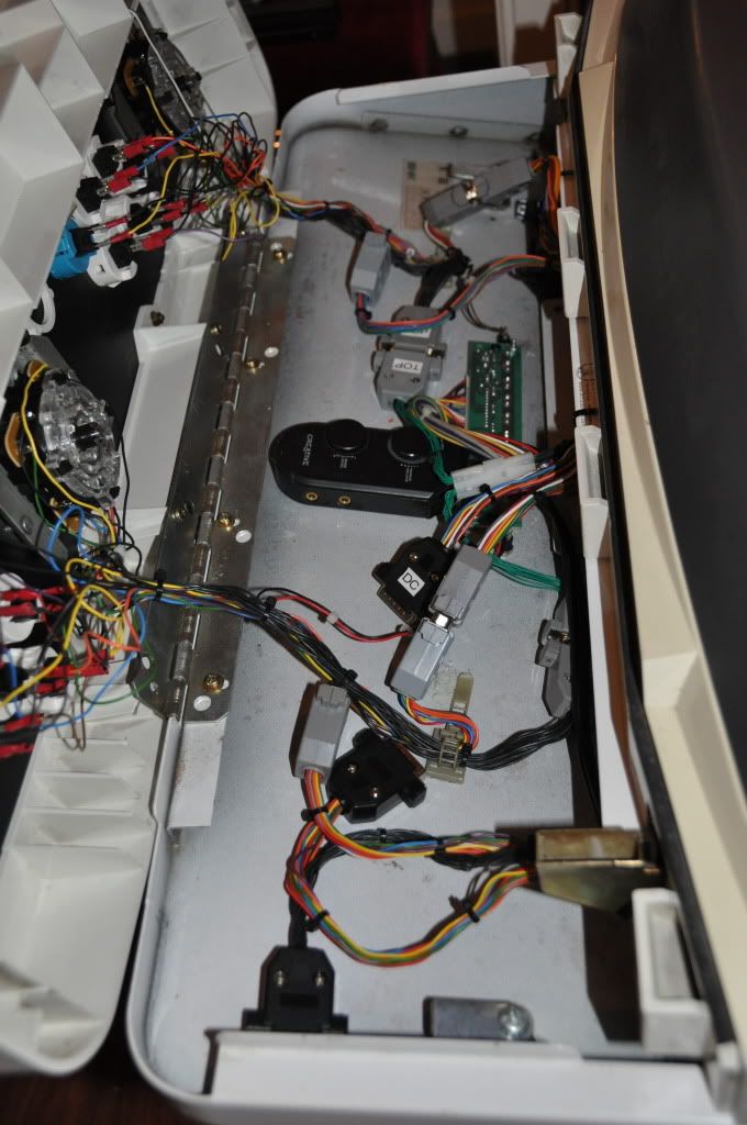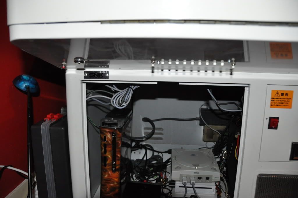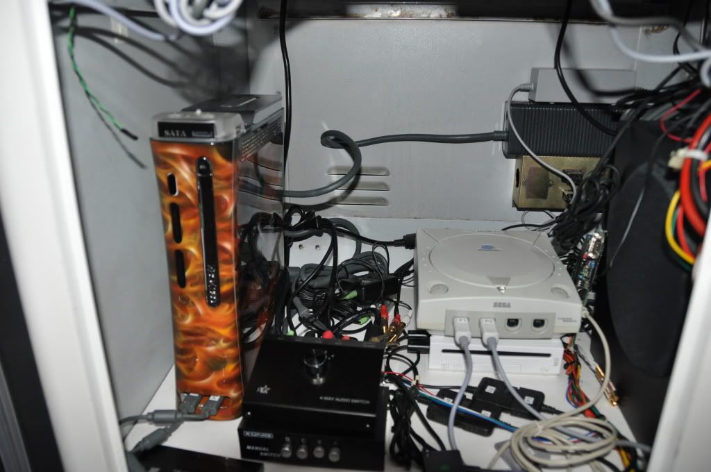
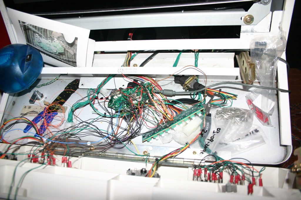
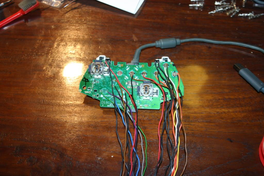
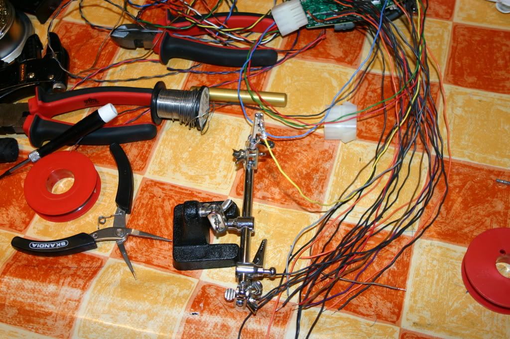
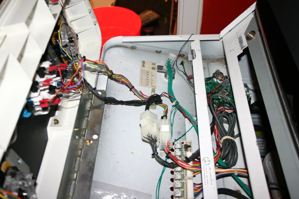
So I run JAMMA, Dreamcast, Gamecube and MAME all in the same cabinet and started the 360 project by looking here and there how to hack the controller. I found some info and that was very useful, especially where the signal and ground points were located. All the other things in my cab have a signal lead and the ground leads are lead to one common ground point. The problem with the 360 is that they all have separate ground points, which really complicates the whole operation when you want them all to run in the same cab. so I was very anxious to hookup the 360 and wanted to be done quickly, after some connecting and disconnecting and a whole lot of wires coming out of my CP I realized this wasn't going to be done the easy way and I knew I hade to rewire the CP form scratch. This was how it looked like when I first started to experiment...
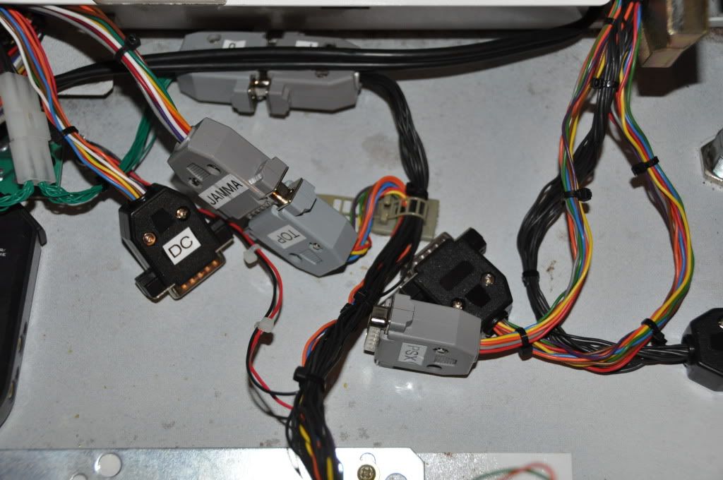
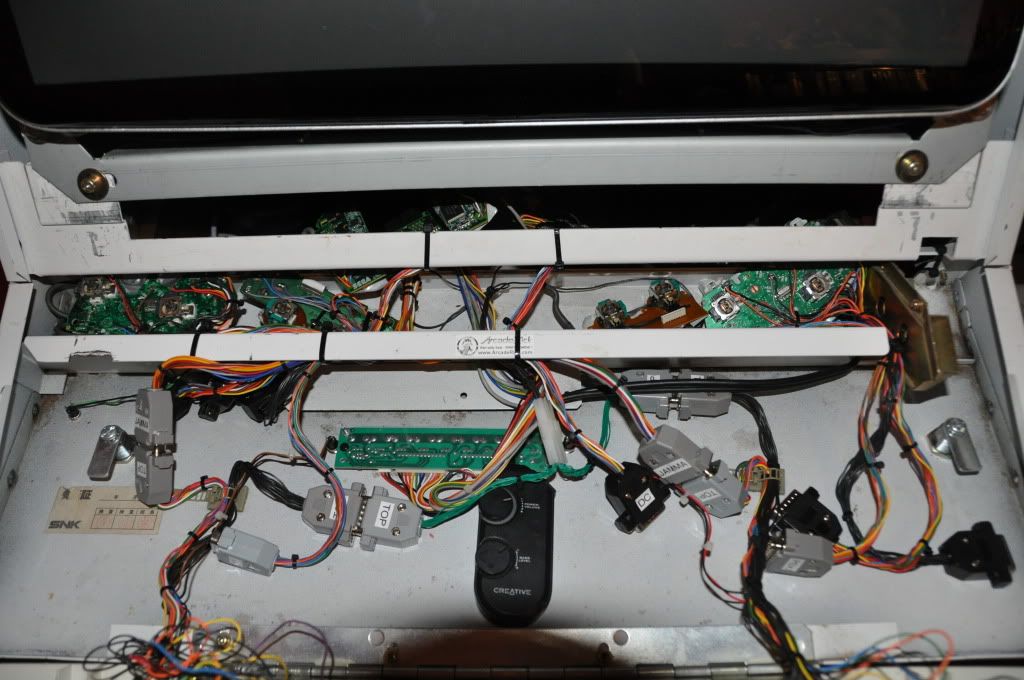
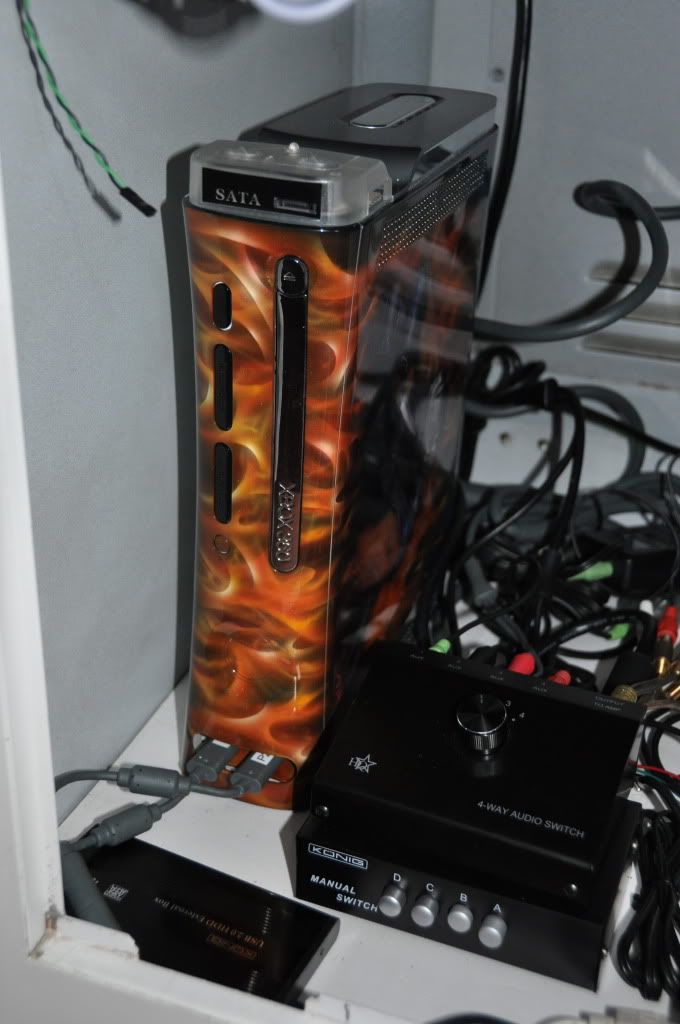
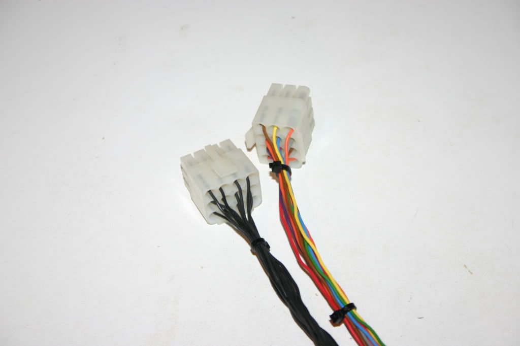
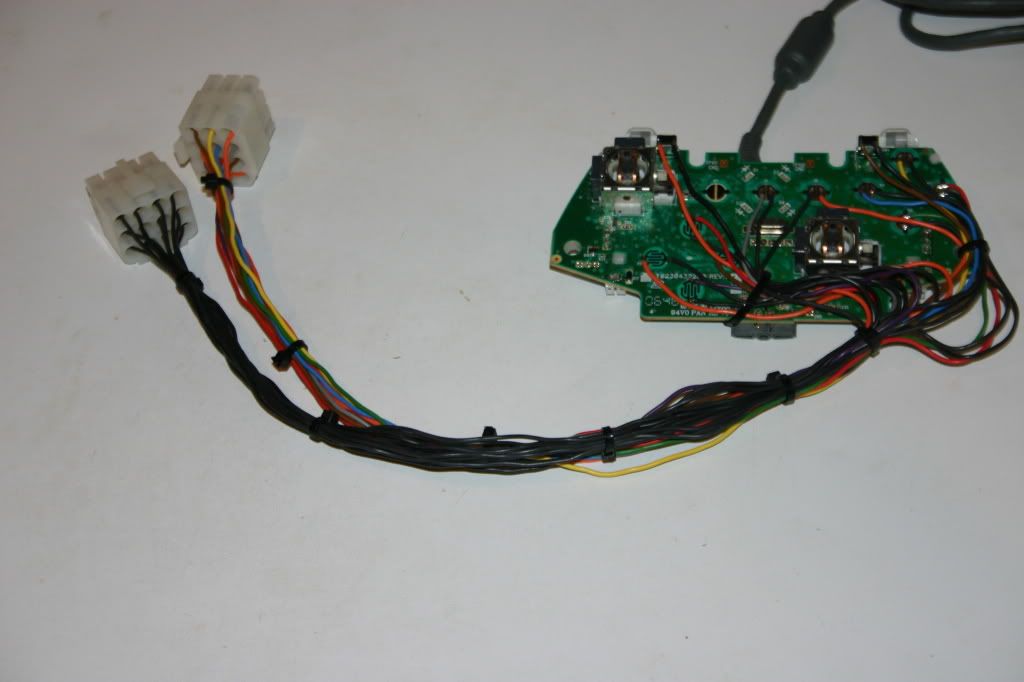
So I had to use 12 pinned molex type connectors to hook and unhook my 360 and the rest when I wanted to play either one of 'em. That's the easiest way to do it, still need to open the CP and switch to connectors, but hey that's a matter of seconds. The connectors the former owner used were like this, it was a disastrous piece of ****, with awfull soledring work, but hey it worked then and I thought if it ain't broken, don't fix it. It allways nagged somehow to renew the whole thing, so this was the perfect oppurtunity...
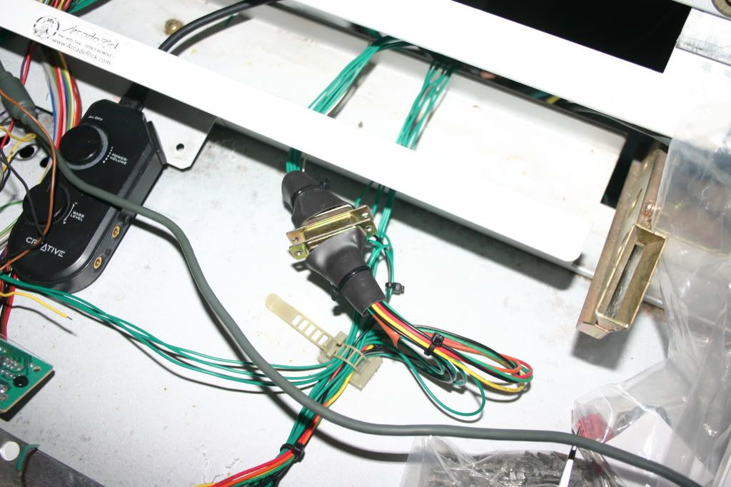
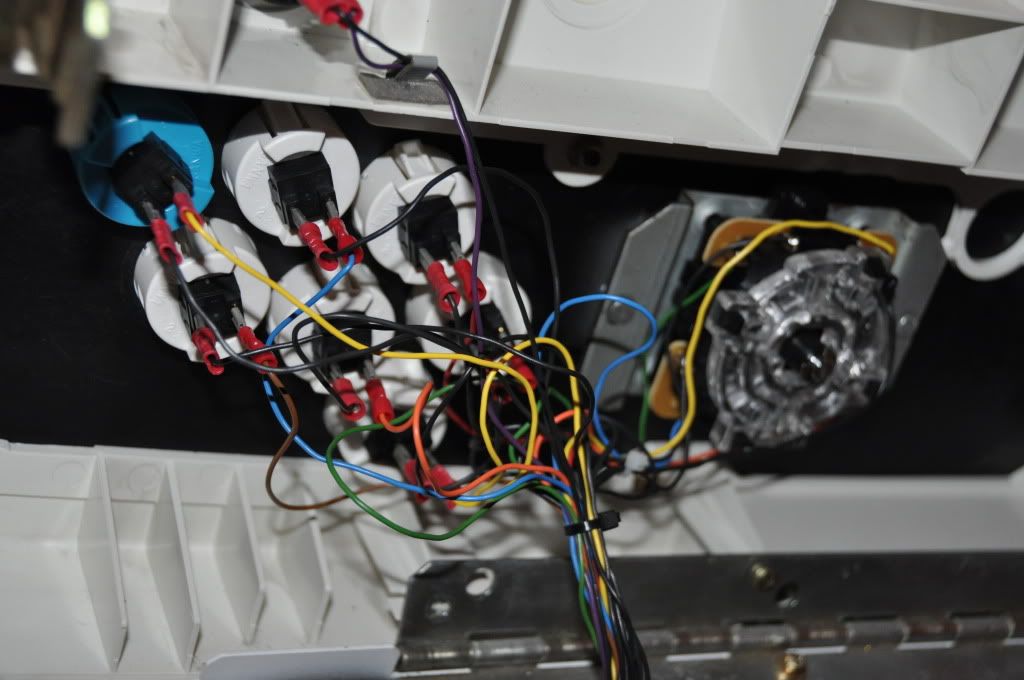
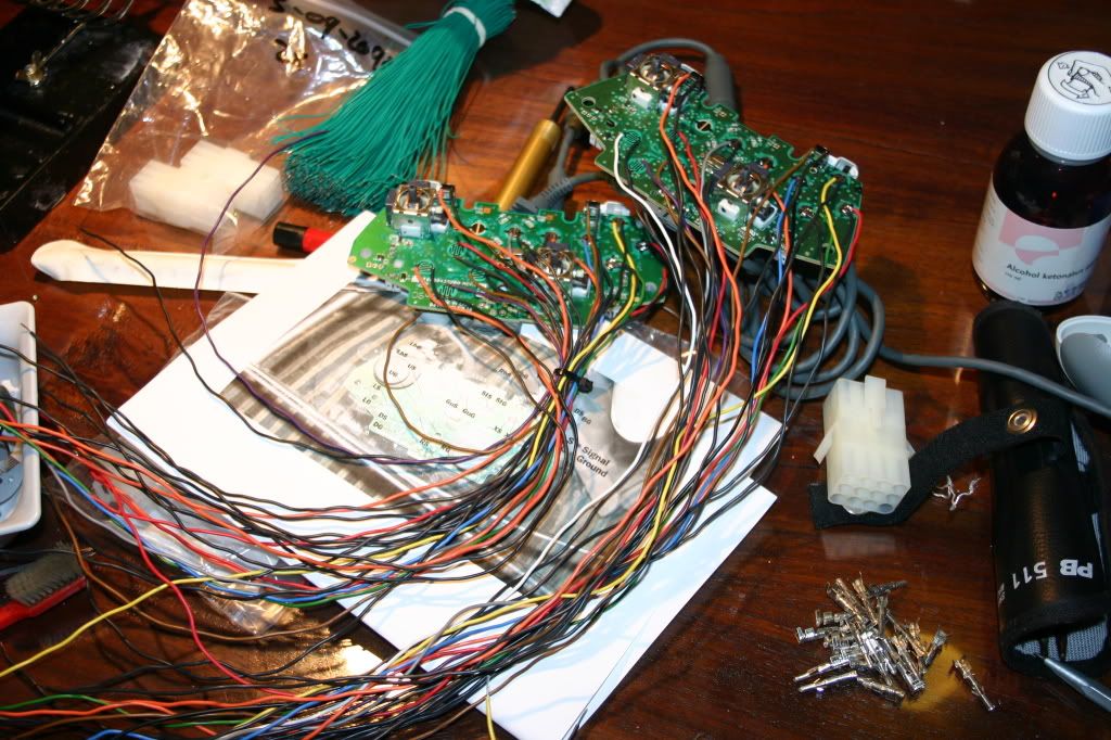
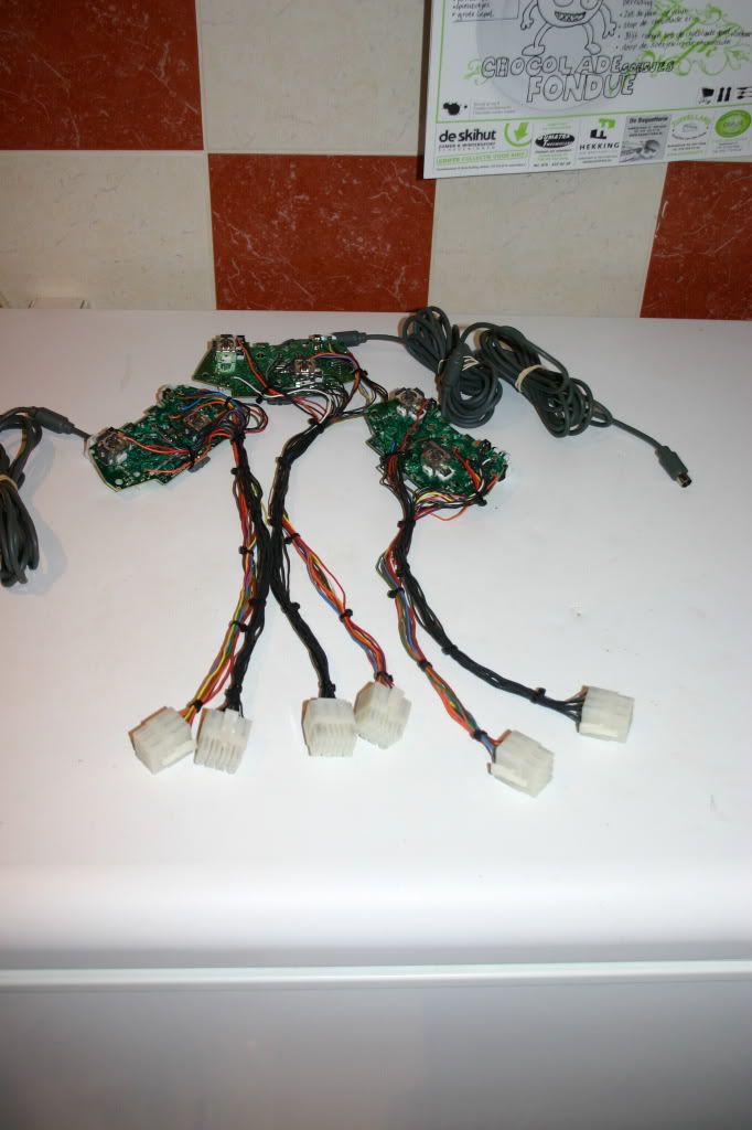
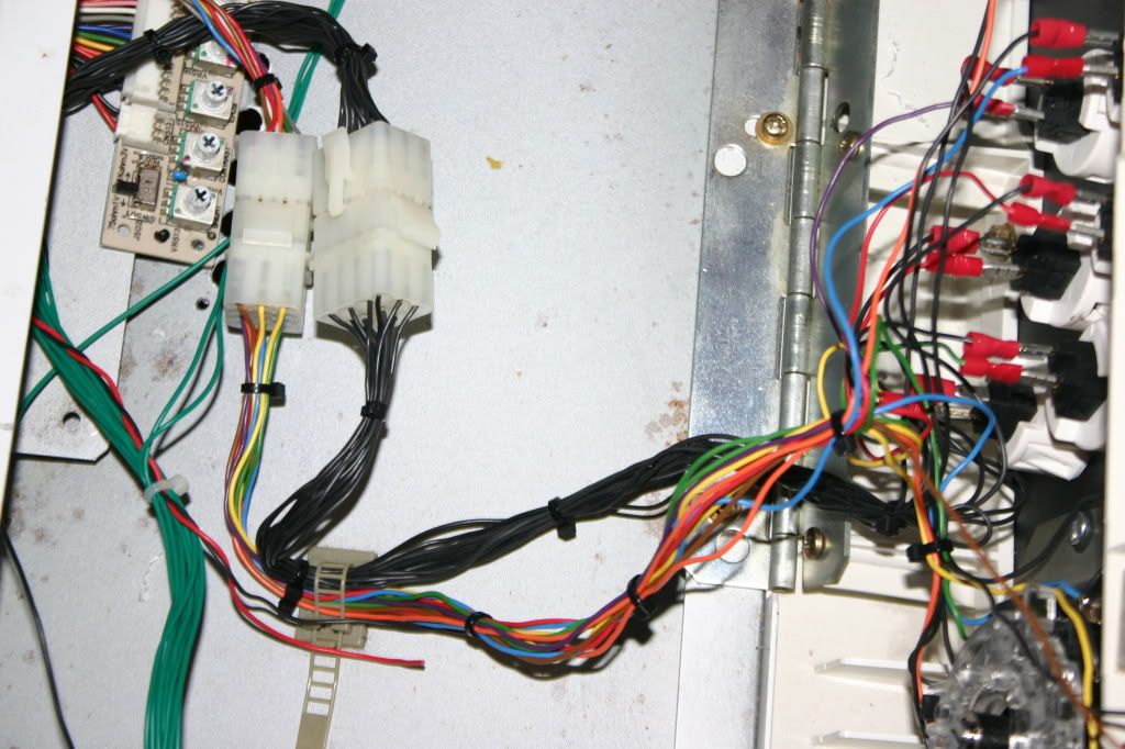
It's also very convenient that he used green wire for everything, but hey the multimeter still does a good job and I left that like that, otherwise I had to rewire the whole cab and that's just too much for now, maybe if I get bored after I finish all my projects. Here's another pic of the old wiring...
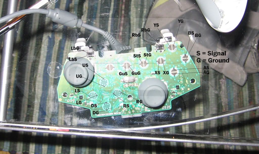
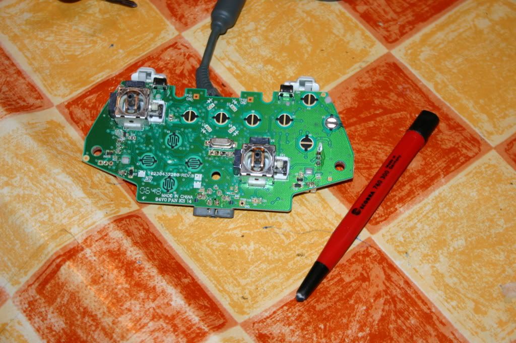
So I found dome tutorials on how to hack the controller and this one was particularly handy, 'cause it tells you what is ground and what's signal.
The wired controller is really opened easily, just some philips screws of which one is hidden under the small rectangular sticker and you're in. There are several ways to scratch away the black stuff on the soldering points. The best and safest way I find is with a glassfiber pen. With this tool it comes of really easy and you can apply really gentle pressure and don't need to be afraid you damage anything. Just scrub gently until you get to the copper points where you apply your solder on later. The pen looks like this..
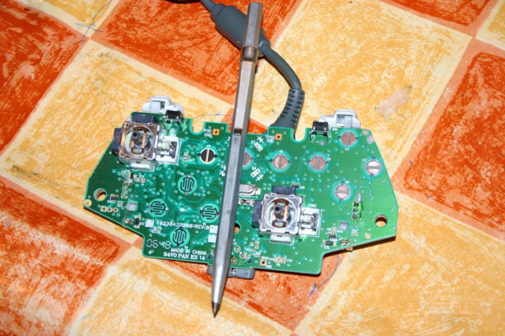
For the smaller points I personally used a preciser tool, but it's not really necessary, but still if your that perfectionist, this is your tool. It's a penlike tool with a very sharp tip, which you scratch of smaal things from prints...
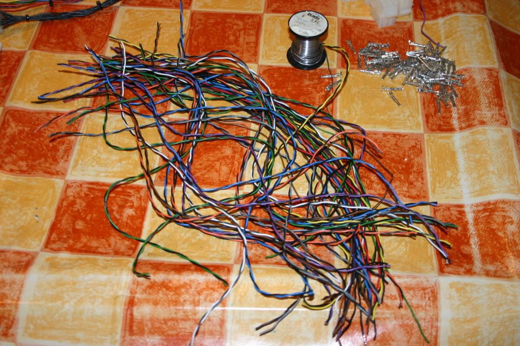
When you've scratched away all the black stuff start presoldering your points, this is very important if you want solder to melt into one with you wire. Btw this a pile of wires you need to start working with
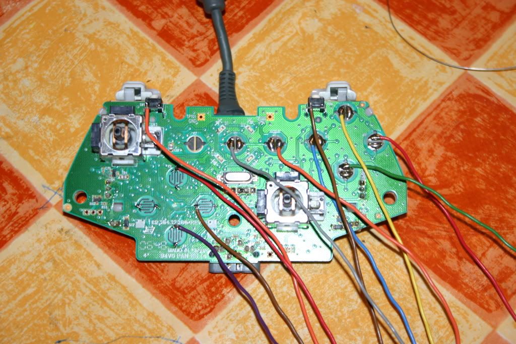
Like I said it's really important to presolder all your soldering points and also the stripped cable ends. You will have perfectly soldered points that won't come of easy, this how it should look like...
Now you're done soldering we need to get them in a molex type connector, the look like this...
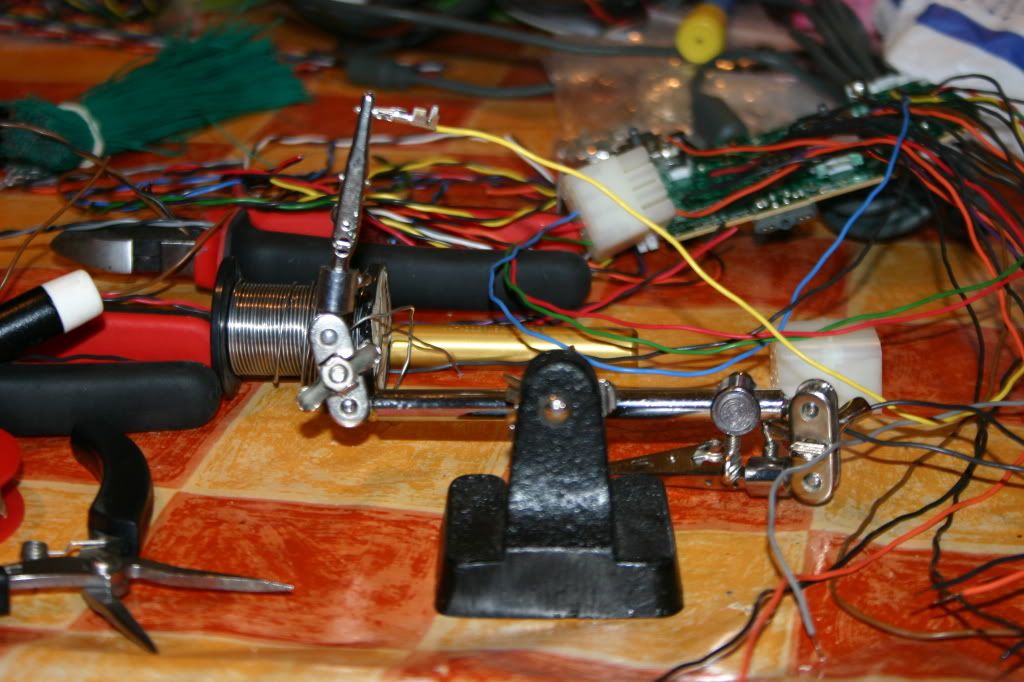
These connectors come with small male and female pins, it's a lot of work to get these soldered and in the right place, but it's the best solution, especially when you want switch connectors between sources now and then. It's very easy to plug in the soldered pins, but getting them out is not so easy. For this you need a special tool which is somewhere around 20 Euro. You can also do without, then you'll just have to push the pin further to the front so it comes out the front where you can desolder or cut of the cable. It's also very handy to have a holder that holds the pins so you can solder them easily, these are cheap and also come with a magnifying glass most of the time. It's allways handy to have one of those around the house. The holder with a pin clamped in...
If you soldered everything and seperated signal form ground it should look like this...
I've arranged the signals in the following order, form the top of the connector down ;
up, down, left, right
A, B, X, Y
LB, RB, Guide, Start
Then you also don't have to really worry about which colour you have used for what, of course if you have enough coloured cables it's also nice to match the colours.
So now you're done with controllers, all you have to do now is make the contra connectors with the buttons and stick coming from the CP. I don't have a really good pic of it yet, but kinda looks like this...
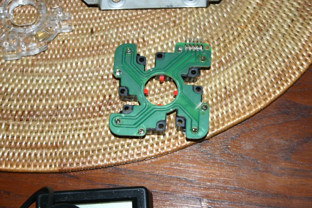
When making the female connector from the CP I encountered a problem, which was that the new type sticks from Sanwa and Seimitsu use the 5 pin cables, these have one common ground pin, which is not what we want of course. So I had to take apart the stick and cut the traces where the ground between the four pins were connected. Just use a sharp cutting knife and cut where the traces are the smallest, then get your multimeter and see if they're still connected. After that you still solder the signal and ground points seperately to your female connector...
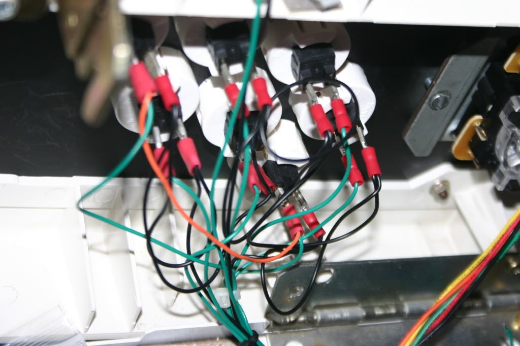
Here I'm presoldering the switches...
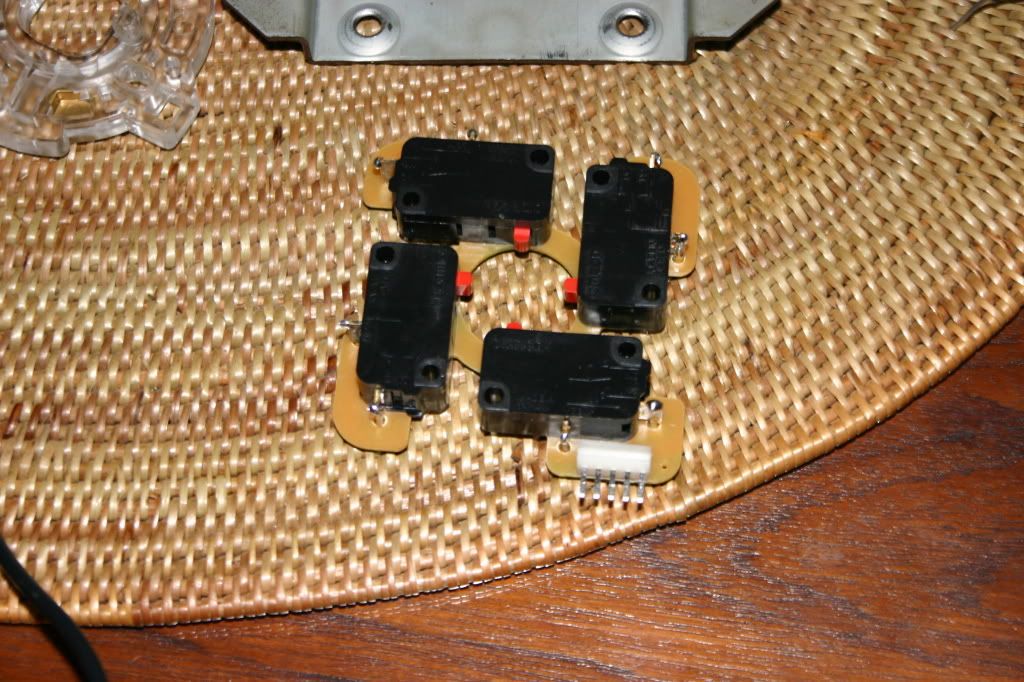
After that put it back together. This is a pic of the ground points on the outside of the stick, they're marked as "com" the rest are the corresponding signals.
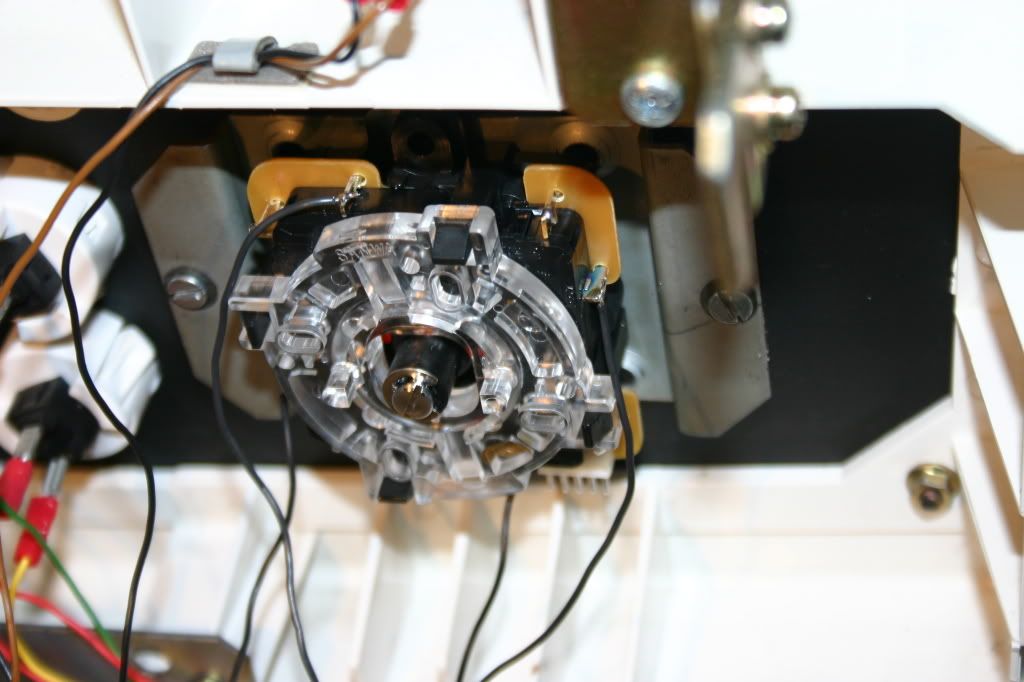
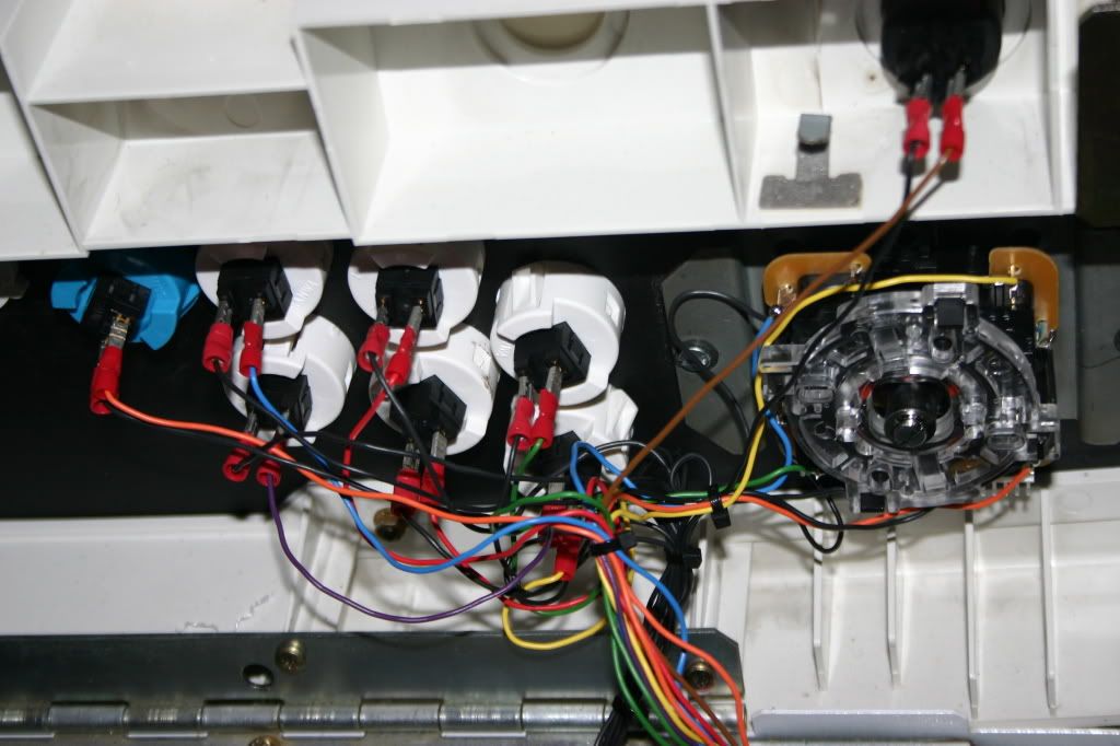
When everything is soldered and neatly tied up it looks like this...
I shall continue tomorrow with connecting the 2nd player and the other connectors, hoefully I'll get it done within a day or 2!
For now you can at least hookup your 360
Have fun!