Felixthedog brought this board round a few months ago to test it in my cabinet as it wouldn't fire up properly at his house. It was missing some key parts and showed signs of being someones repair project / parts board before.
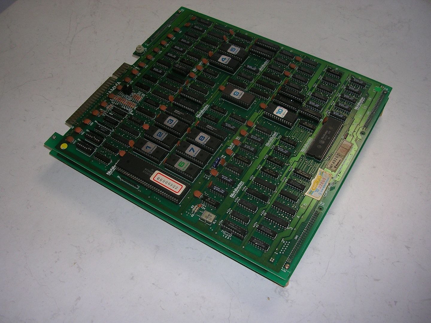
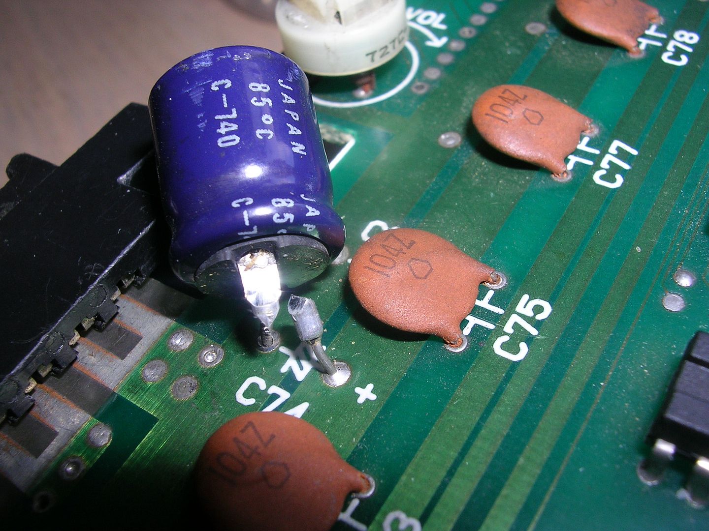
A couple of 74LS257s that decode the dip switches had been removed and replaced with (now empty) sockets, a decoupling capacitor that I am pretty sure was not original (the second board set doesn't have one) had taken a beating...
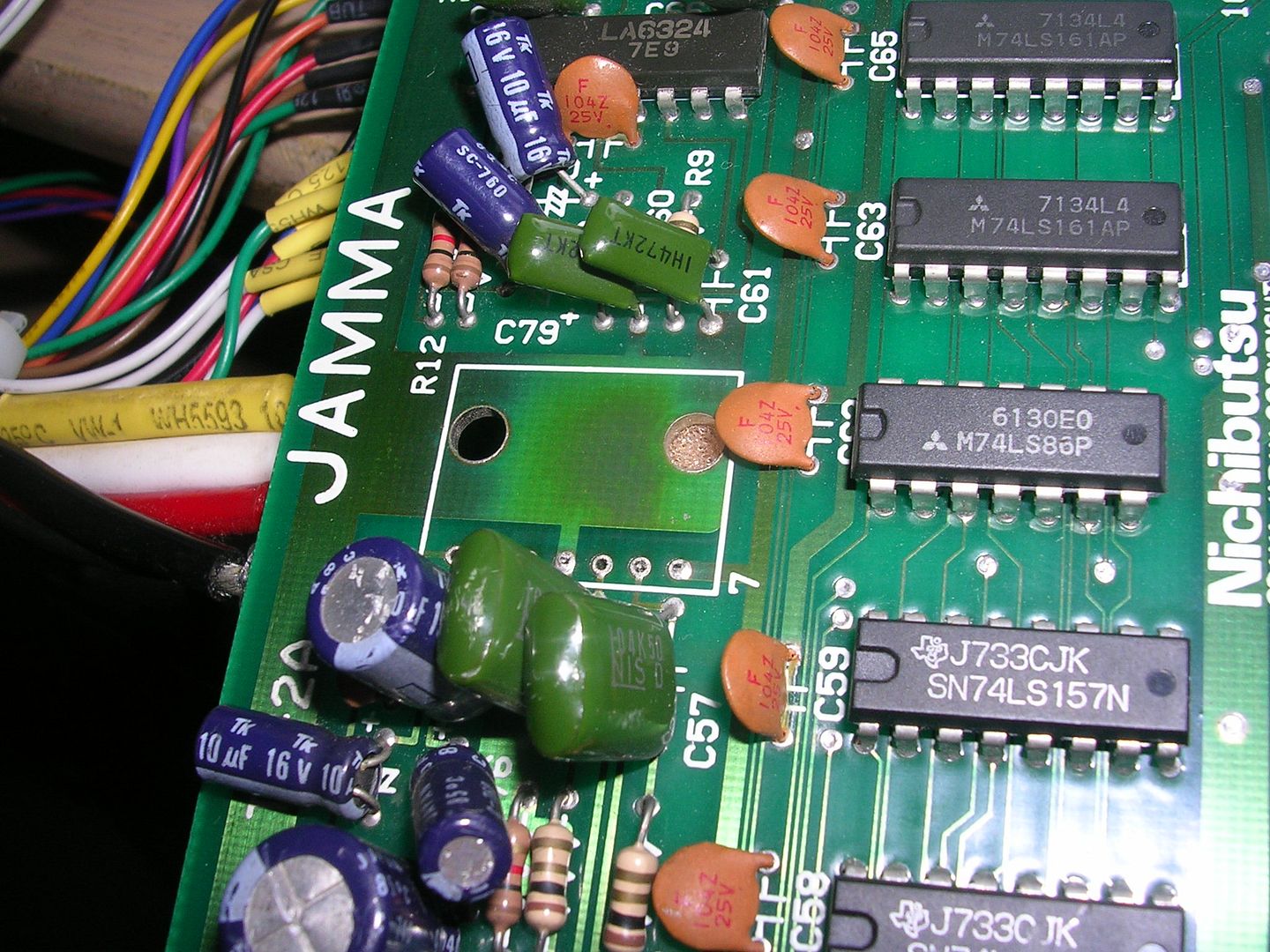
...the amplifier chip had been pinched from the back board...
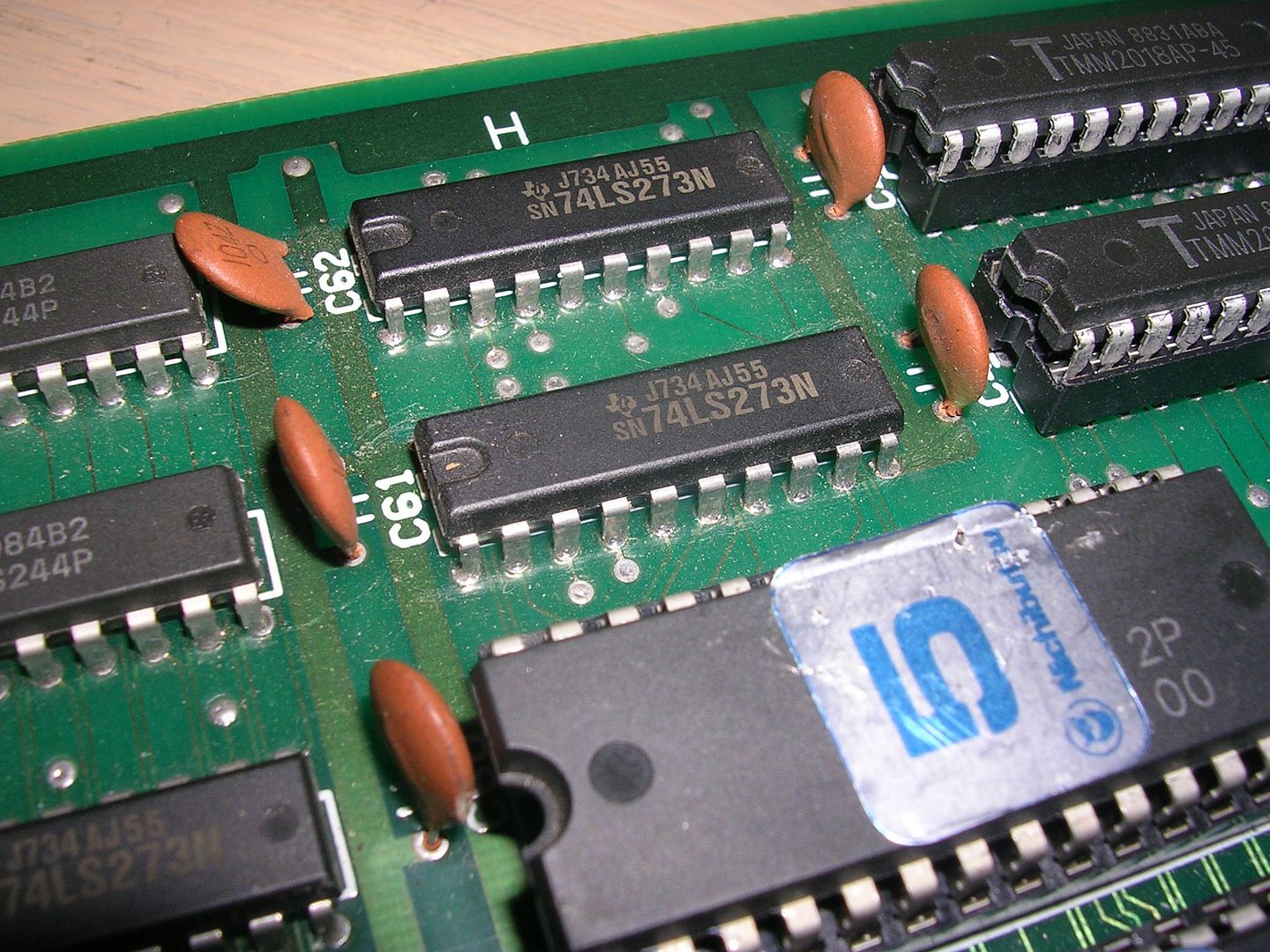
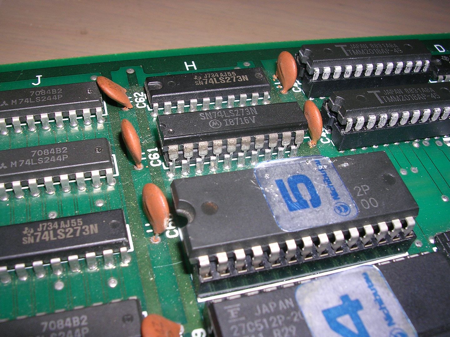
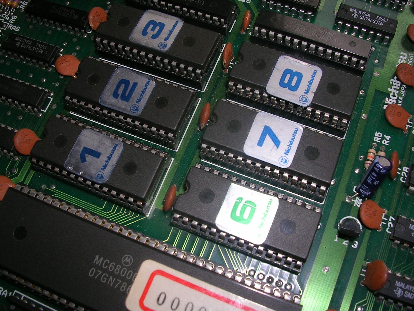
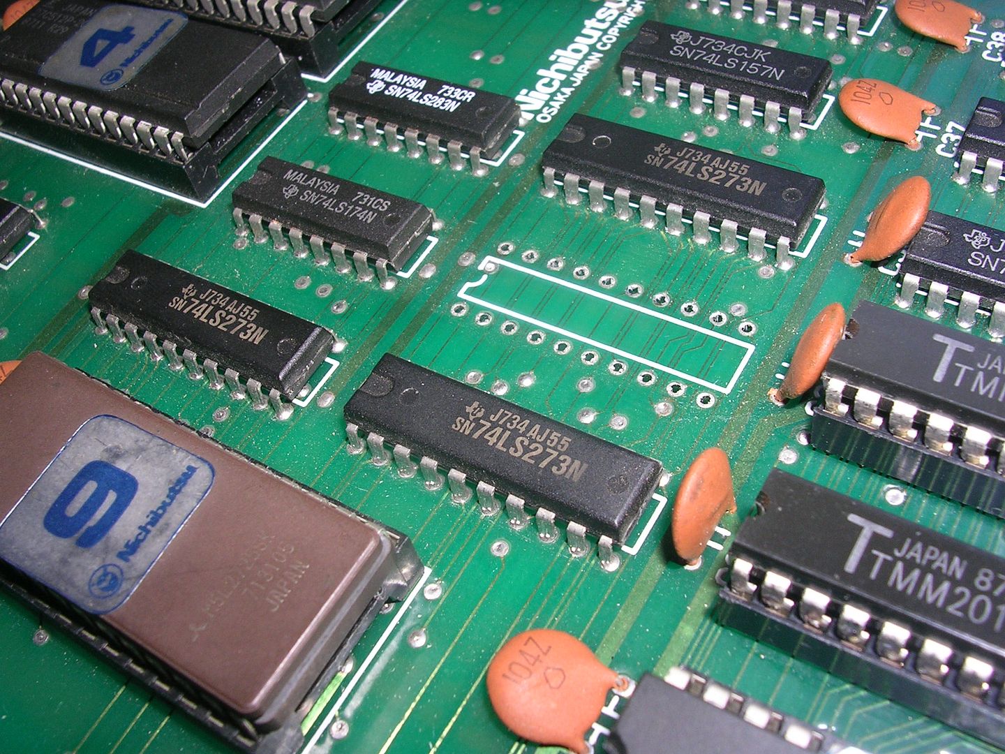
...and there was a chip missing from the top board leaving an empty original 20 pin IC socket.
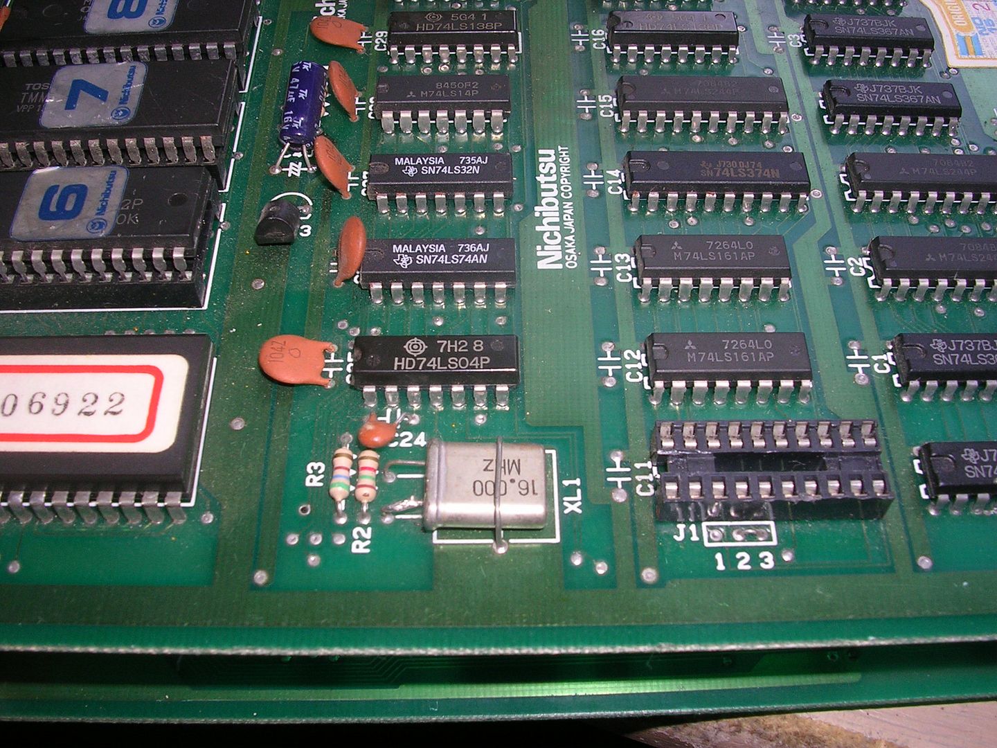
The last bit was the biggest concern, very few ICs on old boards were socketed, and 20 pin usually means a PAL chip. These are configurable logic ICs that take the place of what would be dozens of logic ICs if discrete chips had been used. This means they are highly specific to the board (or board family) and usually cannot be easily replaced. Even though they are programmable it is usually a one way process due to the security bit being set. This usually means a programmed chip cannot be read successfully, so you cannot read the config out of a good one to program another one. Your only hope is that they forgot to set the security bit that day in the factory, which is not very likely. I did fire the board up in my cab and it did precisely nothing, with that chip missing the board was a no hoper unless a donor board could be found so I didn't investigate it any further.
Fast forward 3 months and Felixthedog had sourced a donor PCB, another faulty PCB set but one that was complete. Initially that board set looked like a better repair candidate but not for long. This one had been someones repair project and they had made a mess in a number of areas. They had re-soldered all the PCB connectors and then over tightened bolts holding the board together. The soldering was messy and with the stress on the boards some of the pins had been forced through which tears the plate through holes, meaning a lot of the joints would be unreliable. The board also showed signs it had been wet at one stage, with corrosion and track damage under a number of the ROMs, and the ROM legs oxidised to the point that a number couldn't be read, ut it did have the PAL chip that was missing from the other board.
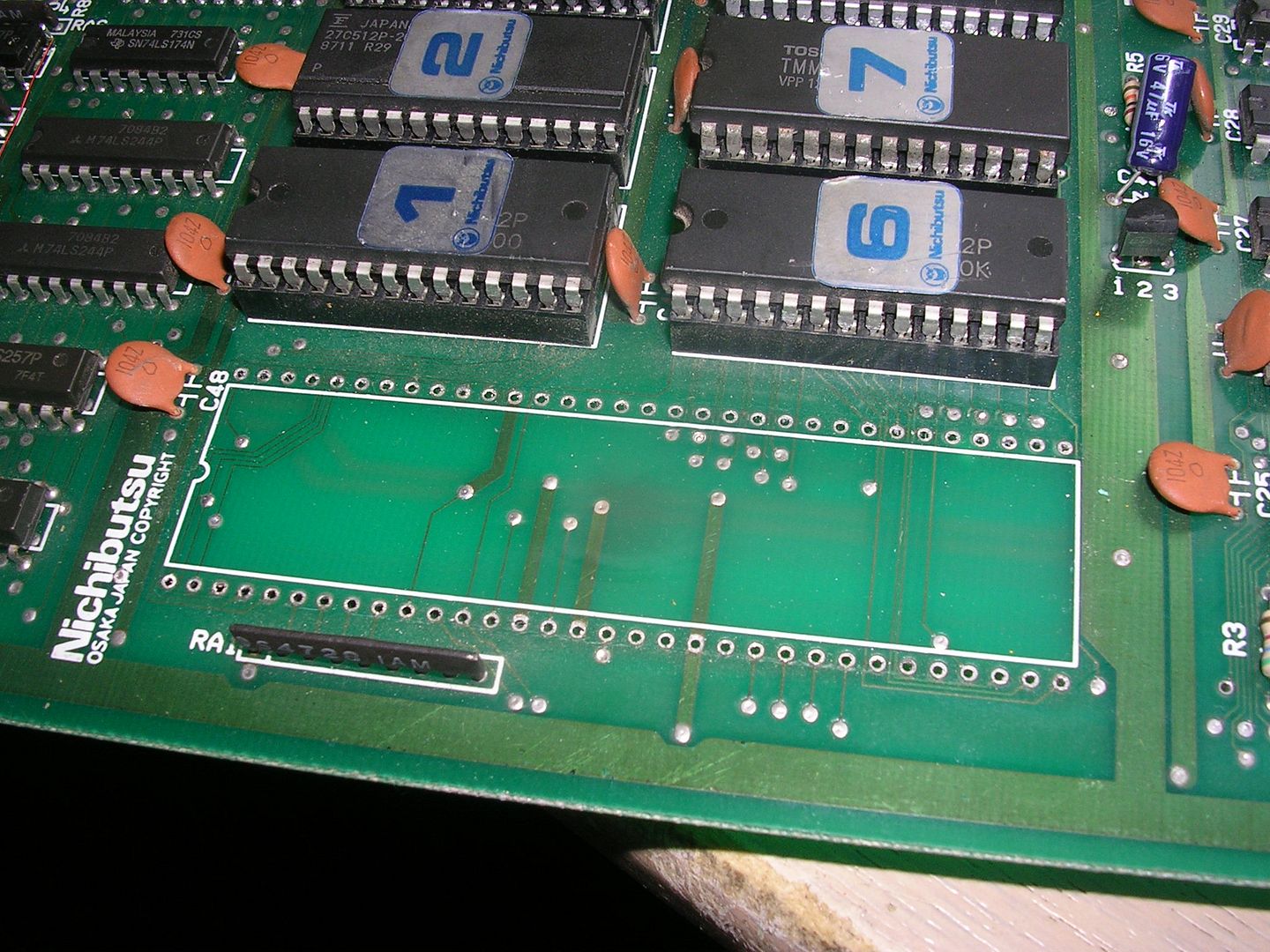
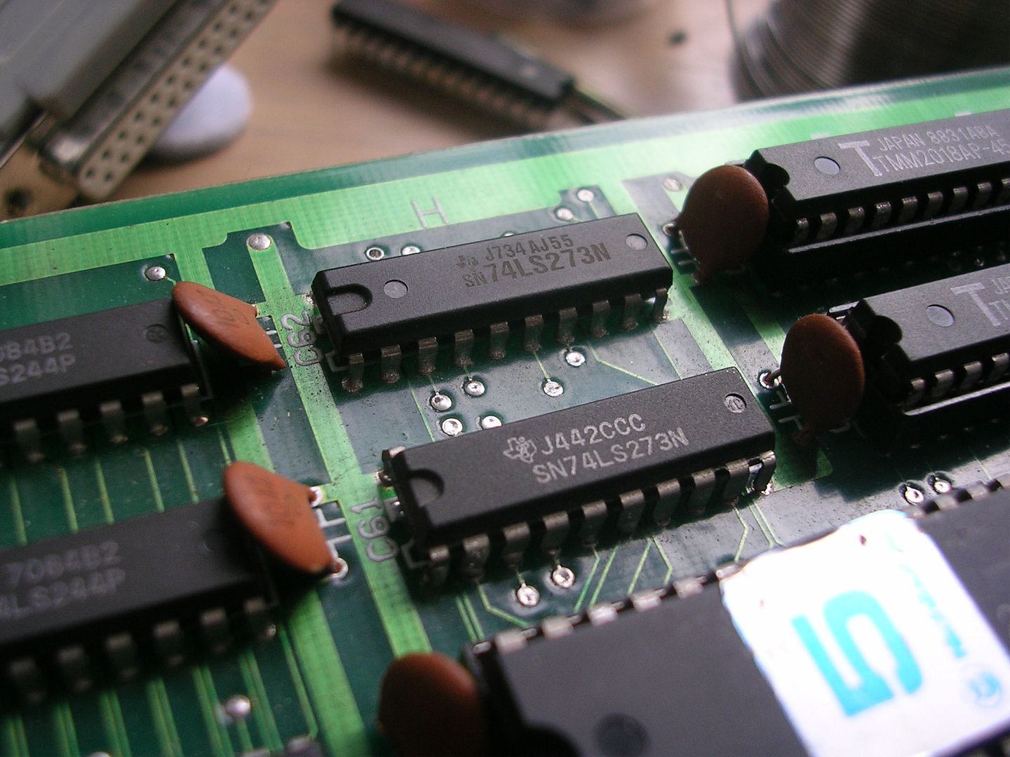
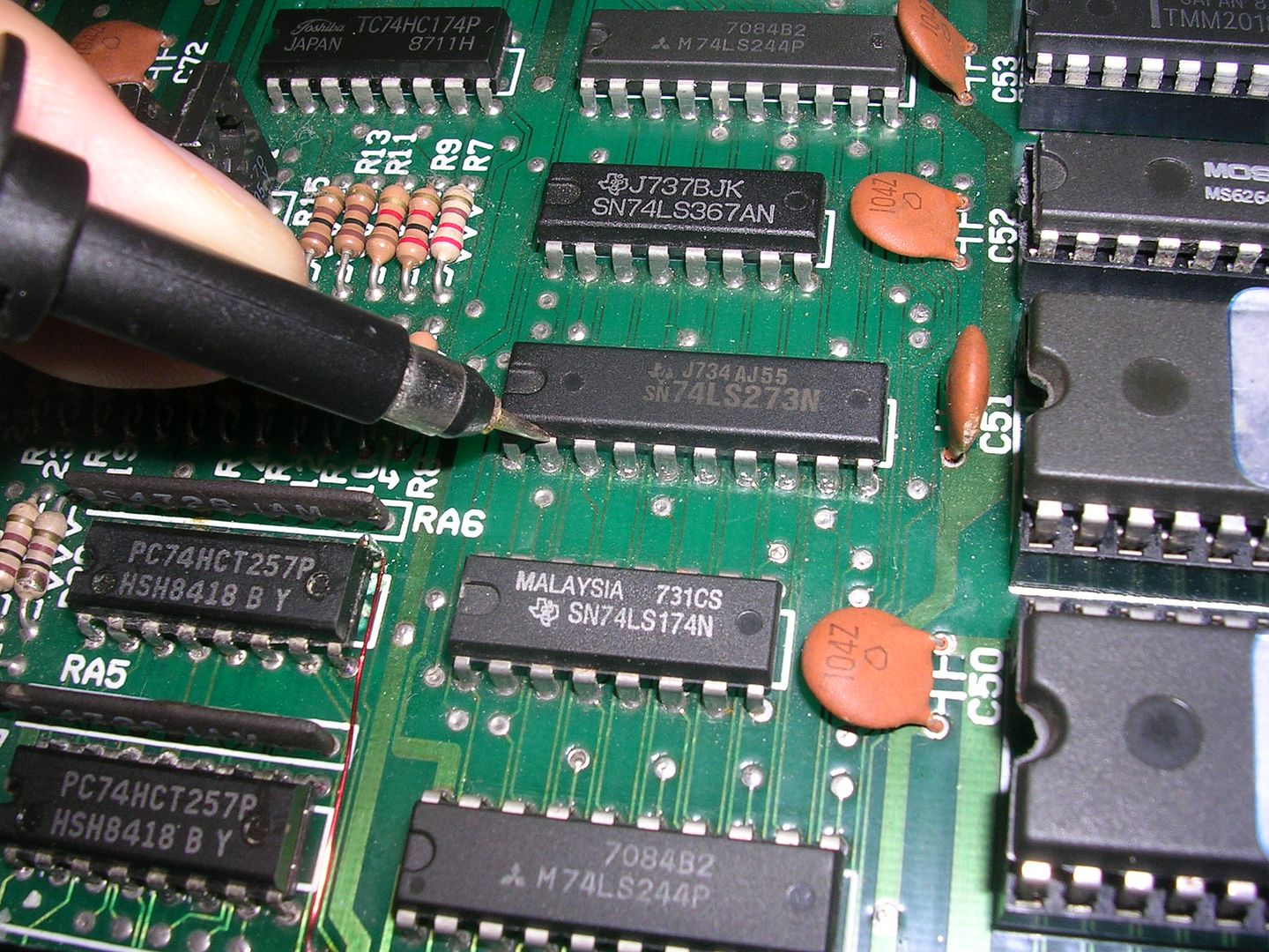
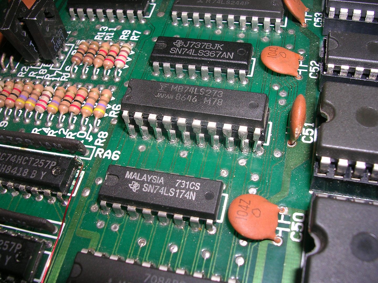
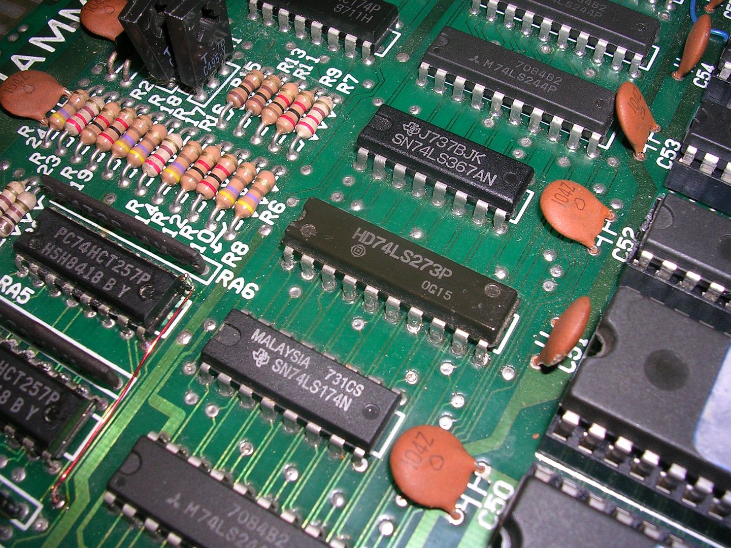
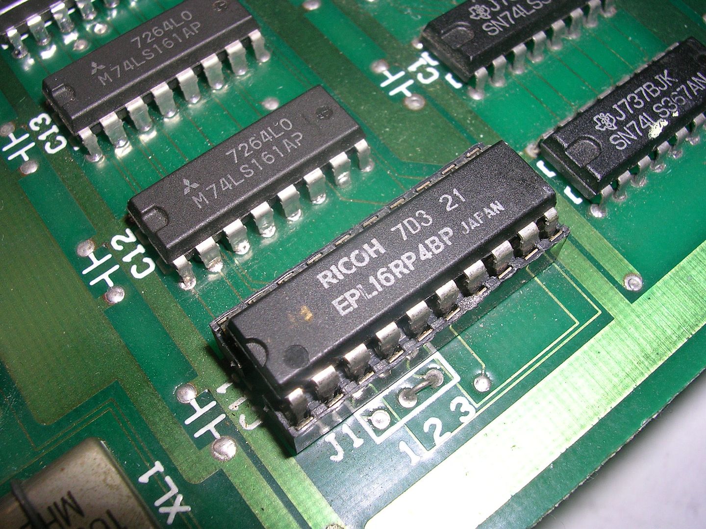
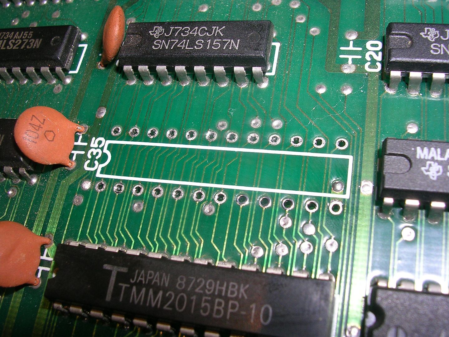
Swapping the PAL into the original board...
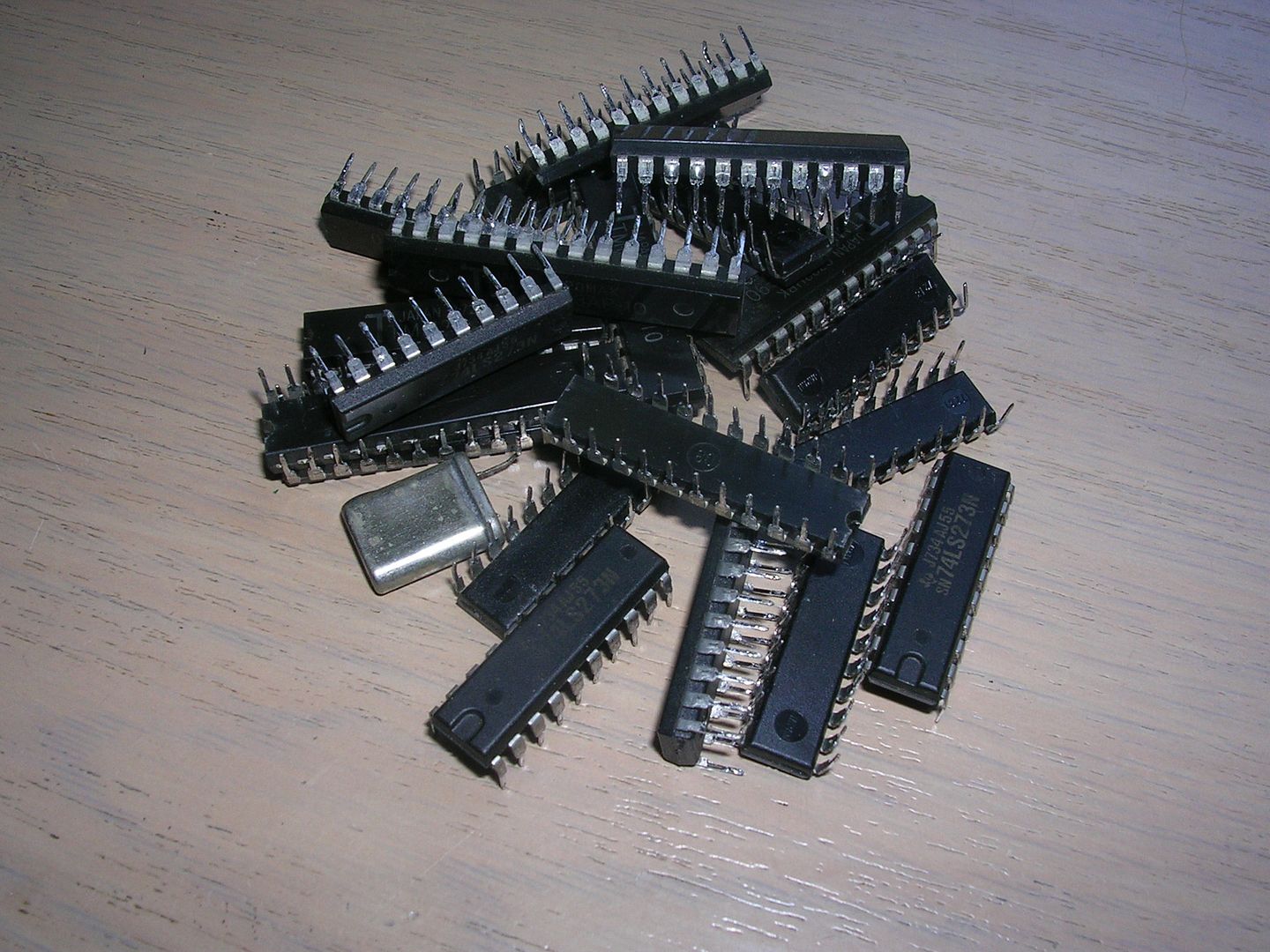
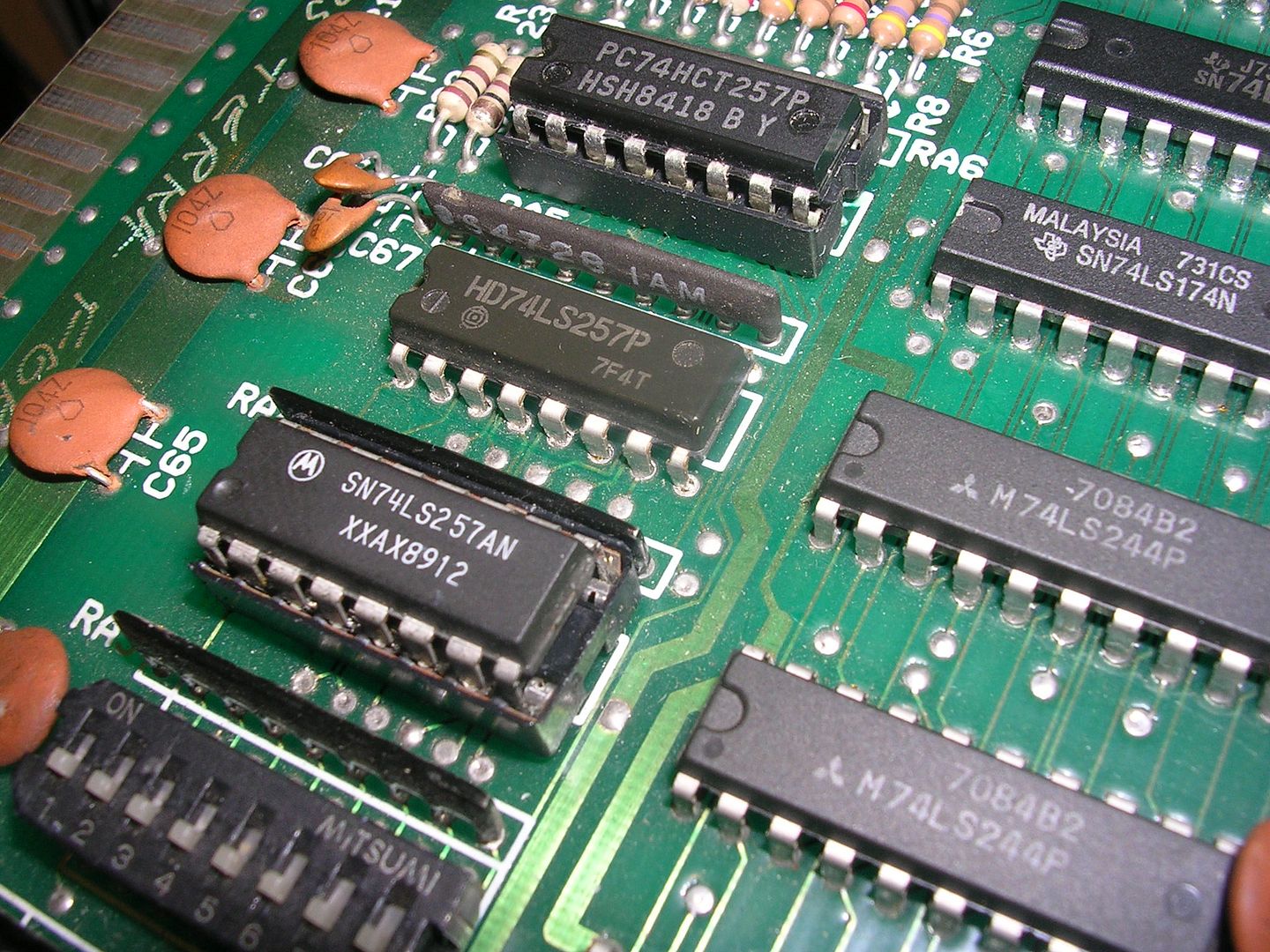
... and dropping in a couple of 74LS257s ...
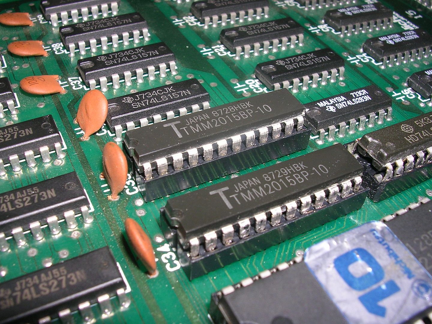
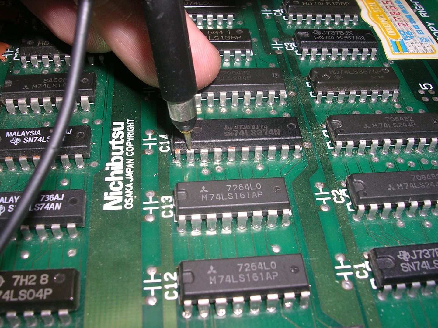
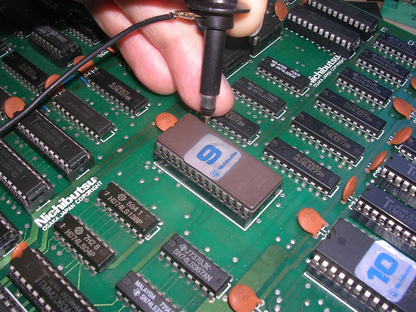
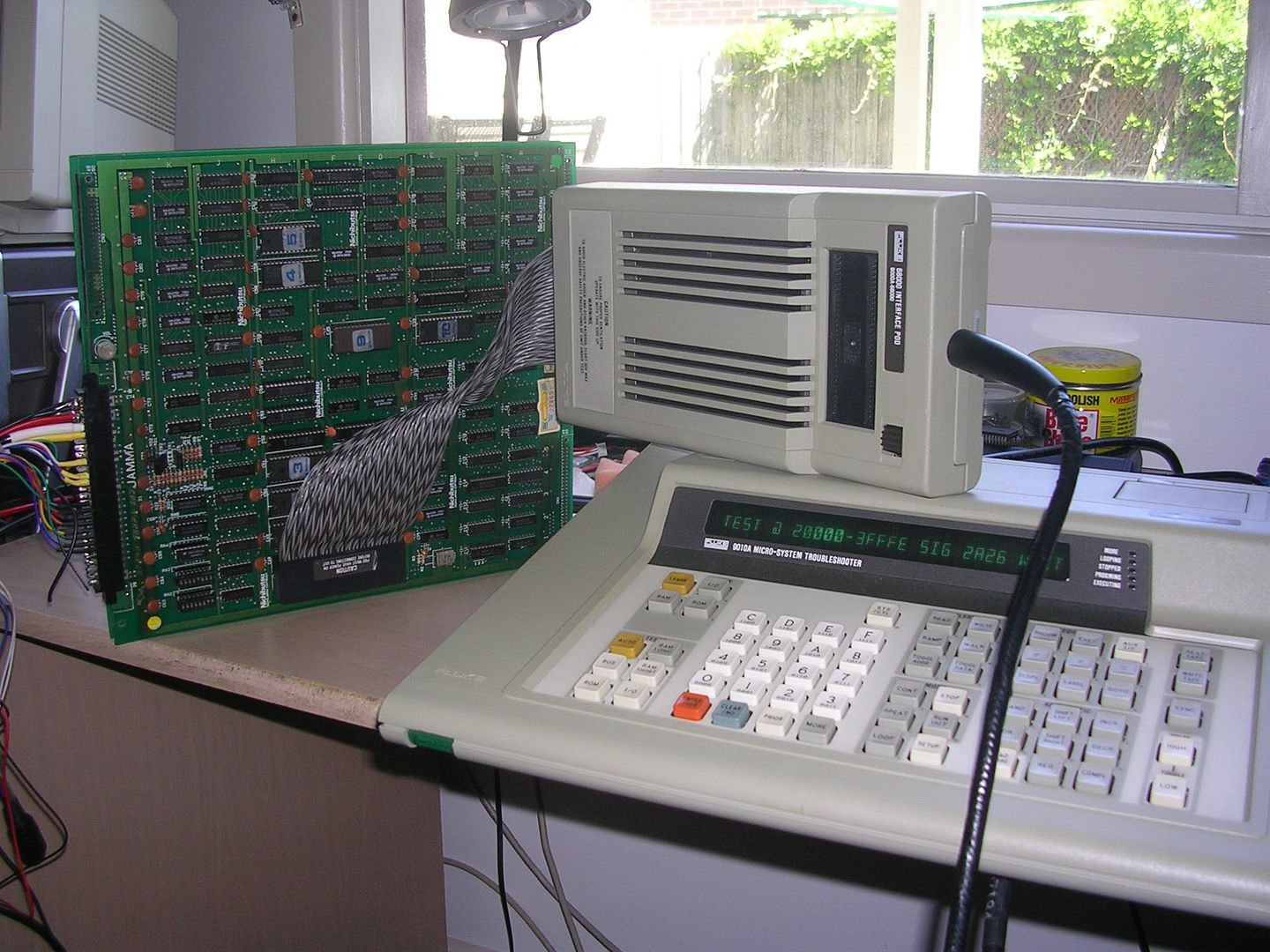
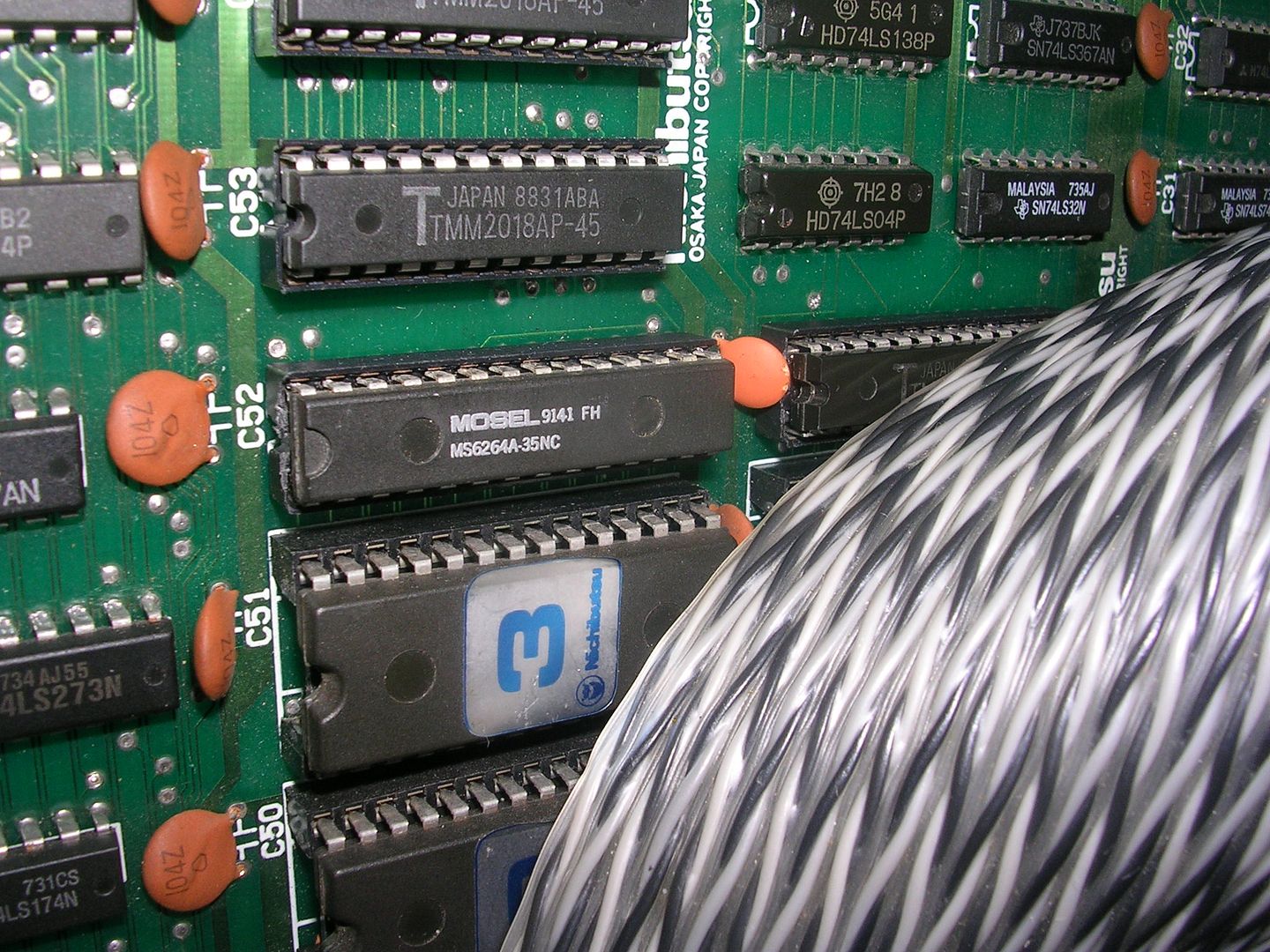
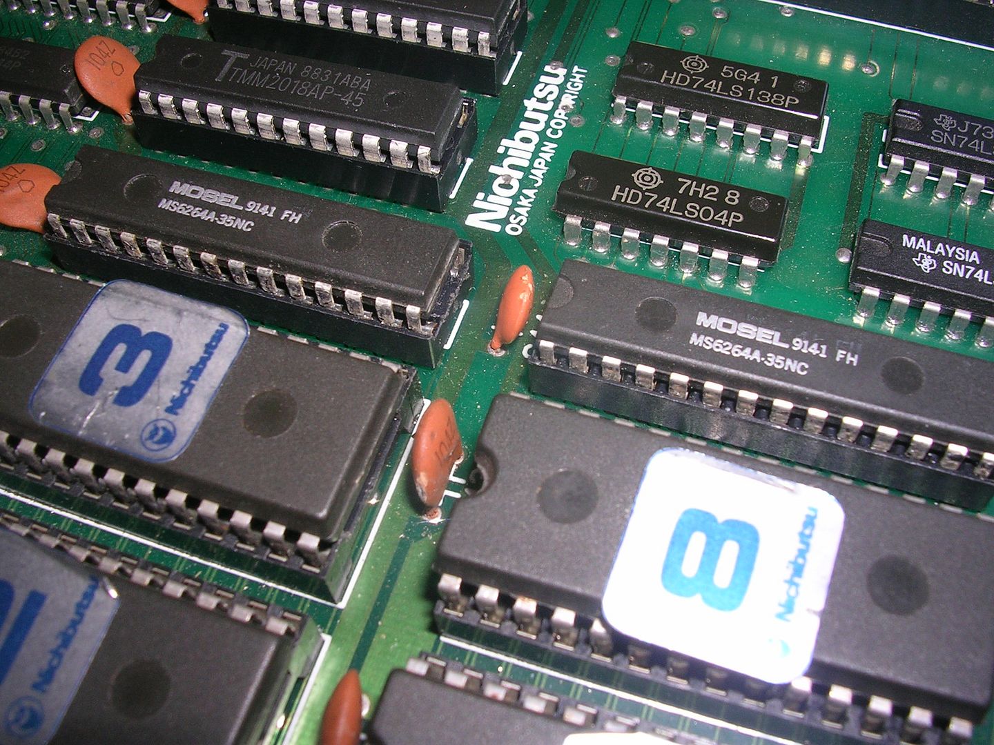
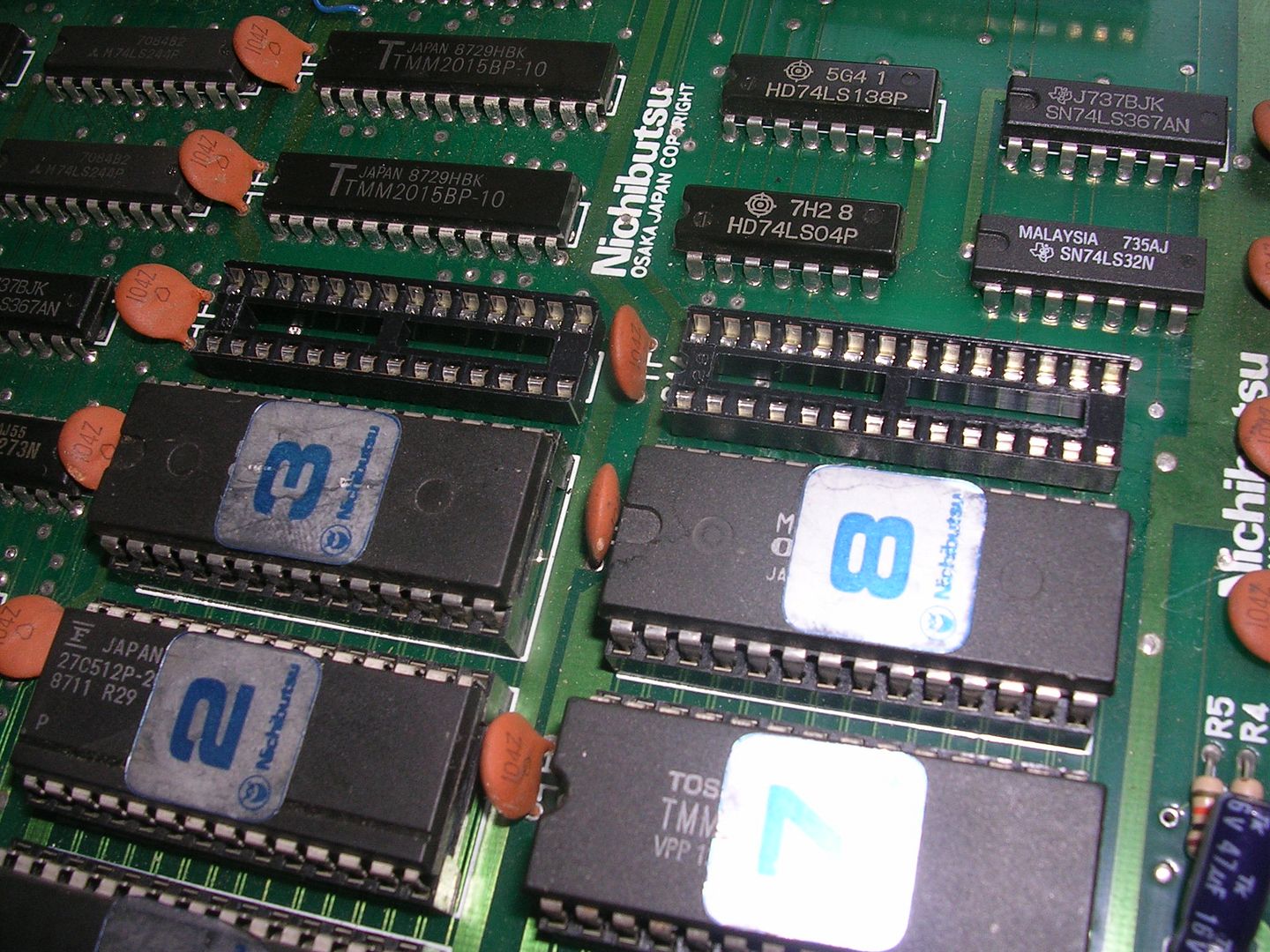
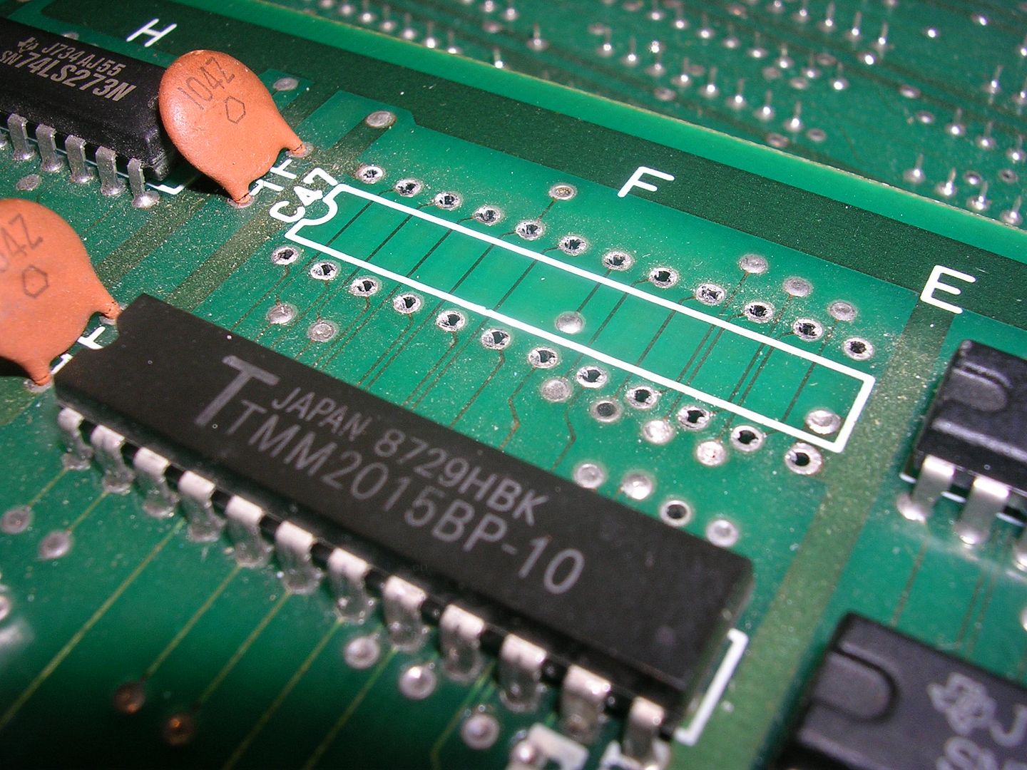
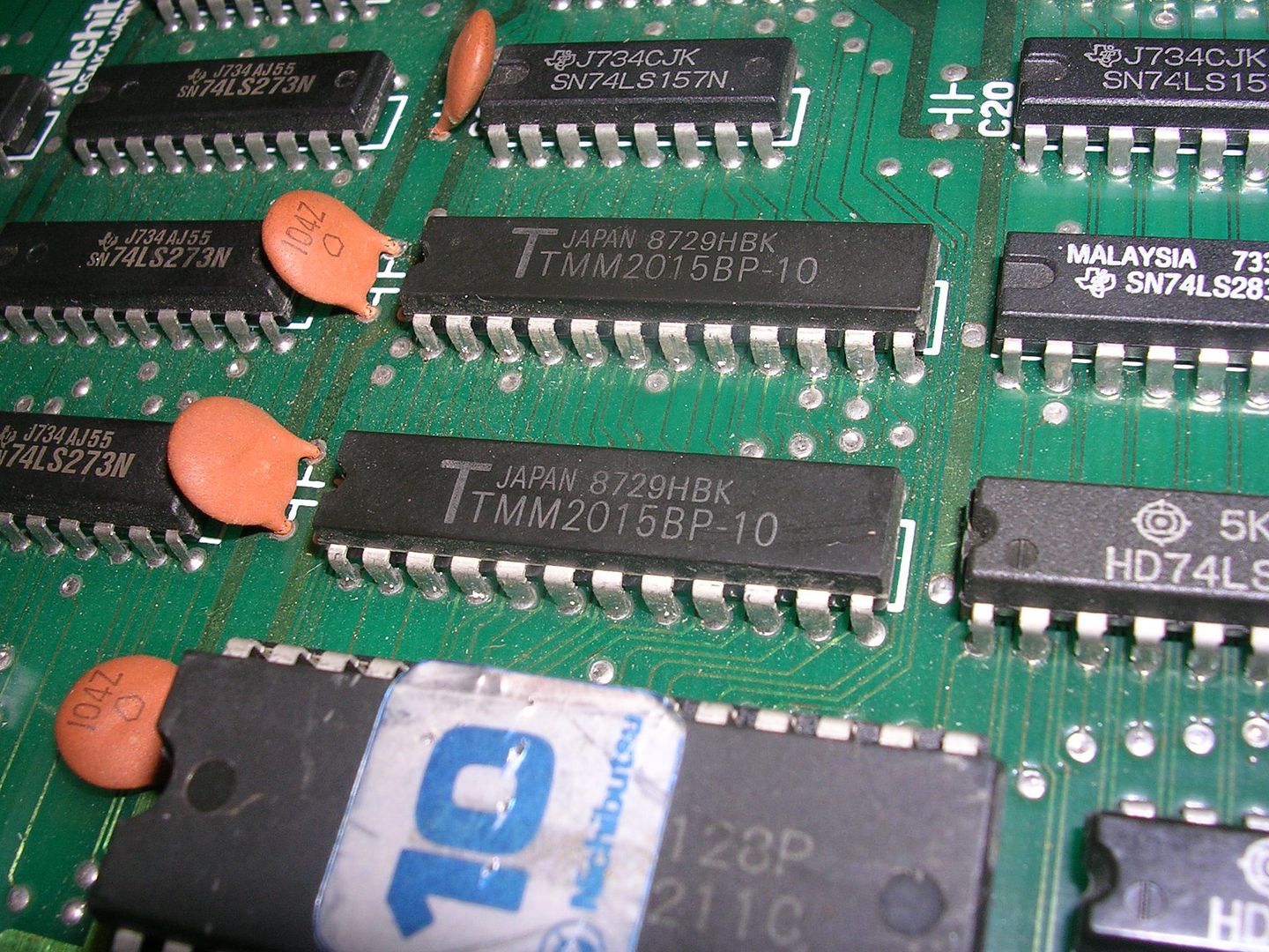
...resulted in not much, basically a stone dead board. Oscilloscope time, hitting up the 68000 CPU showed I had clock, and that /HALT and /RESET were both high, so the board should be running. At the exact instant of power up the board did give a burst of activity on the CPU address lines at the ROMs but then went quiet, a good sign that the CPU is crashing, probably because it has no working RAM, or because the program code in the ROMs is corrupted. The main system RAM was a pair of Toshiba TMM2063 ICs with the shiny black tops...
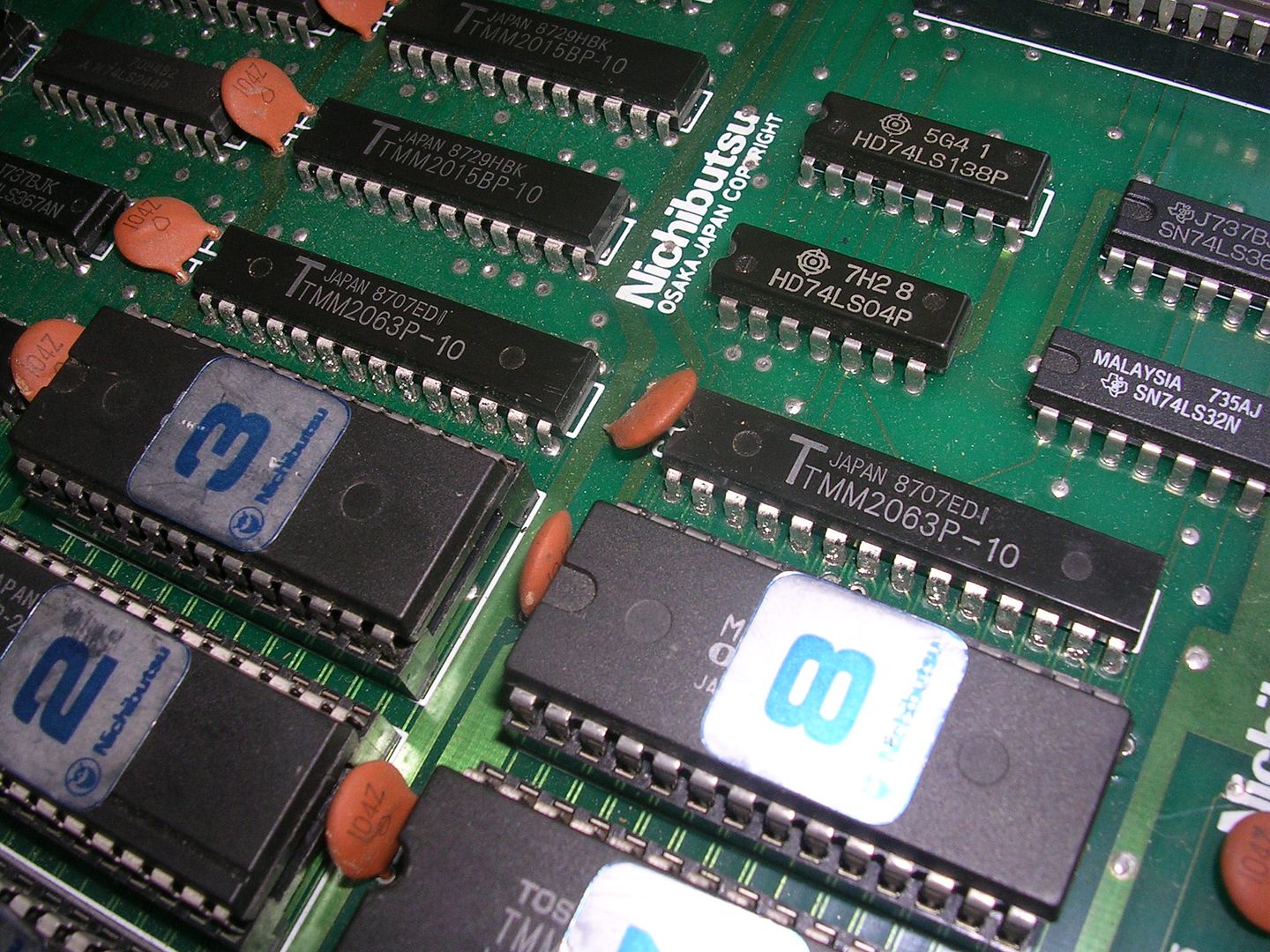
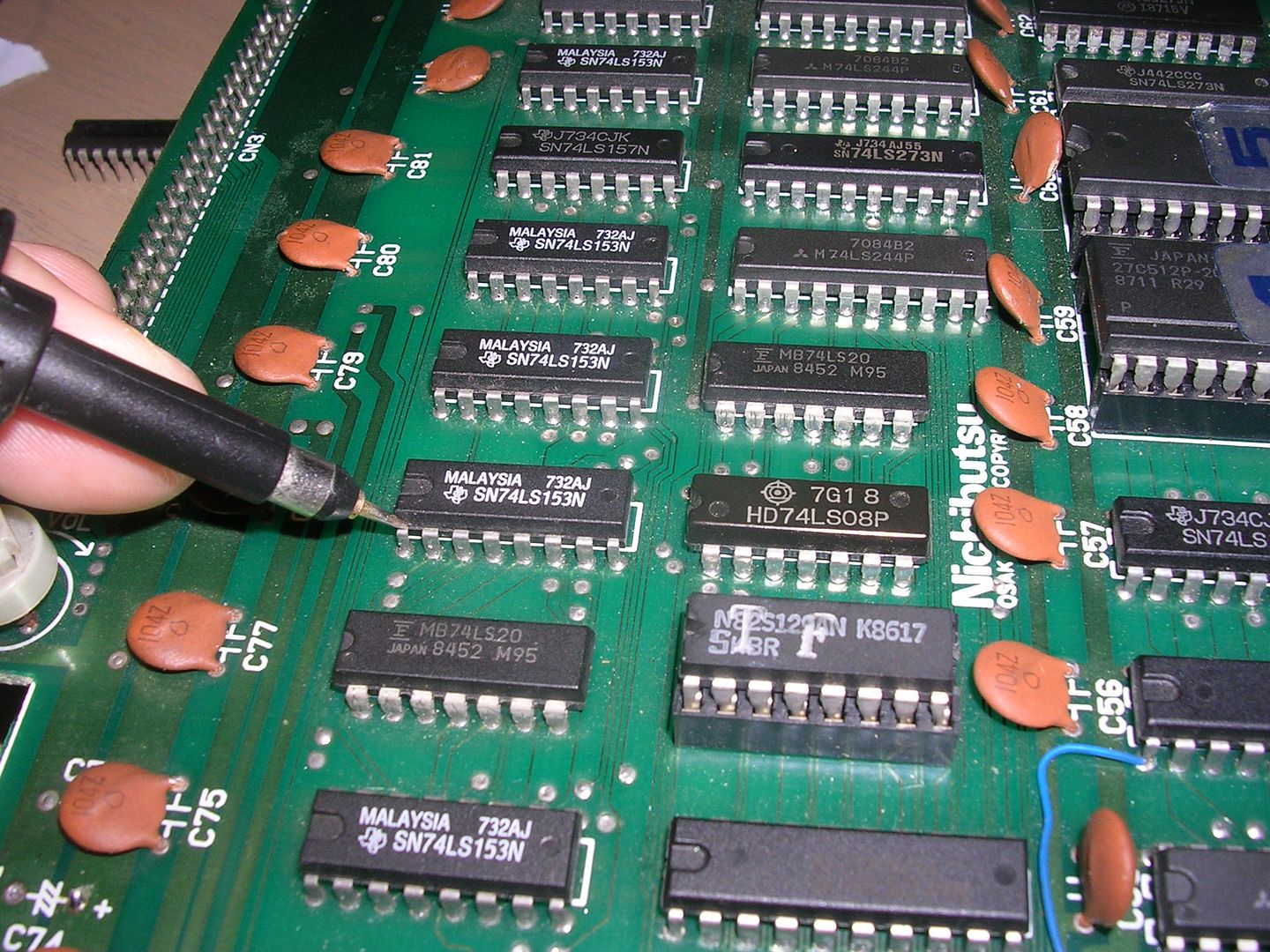
...which are almost always dead on faulty boards, but as the ROMs were socketed I ran them all through the EPROM reader to check I wasn't looking for a hardware solution to a software problem. All the ROMs checked out and the output from the RAMs looked suspect.
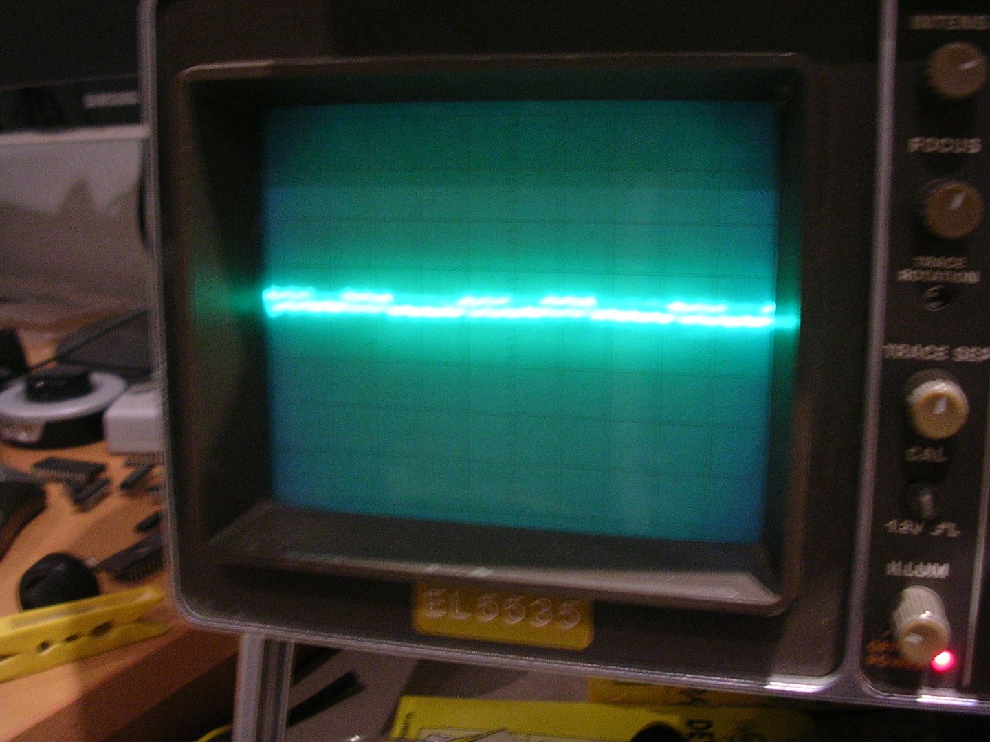
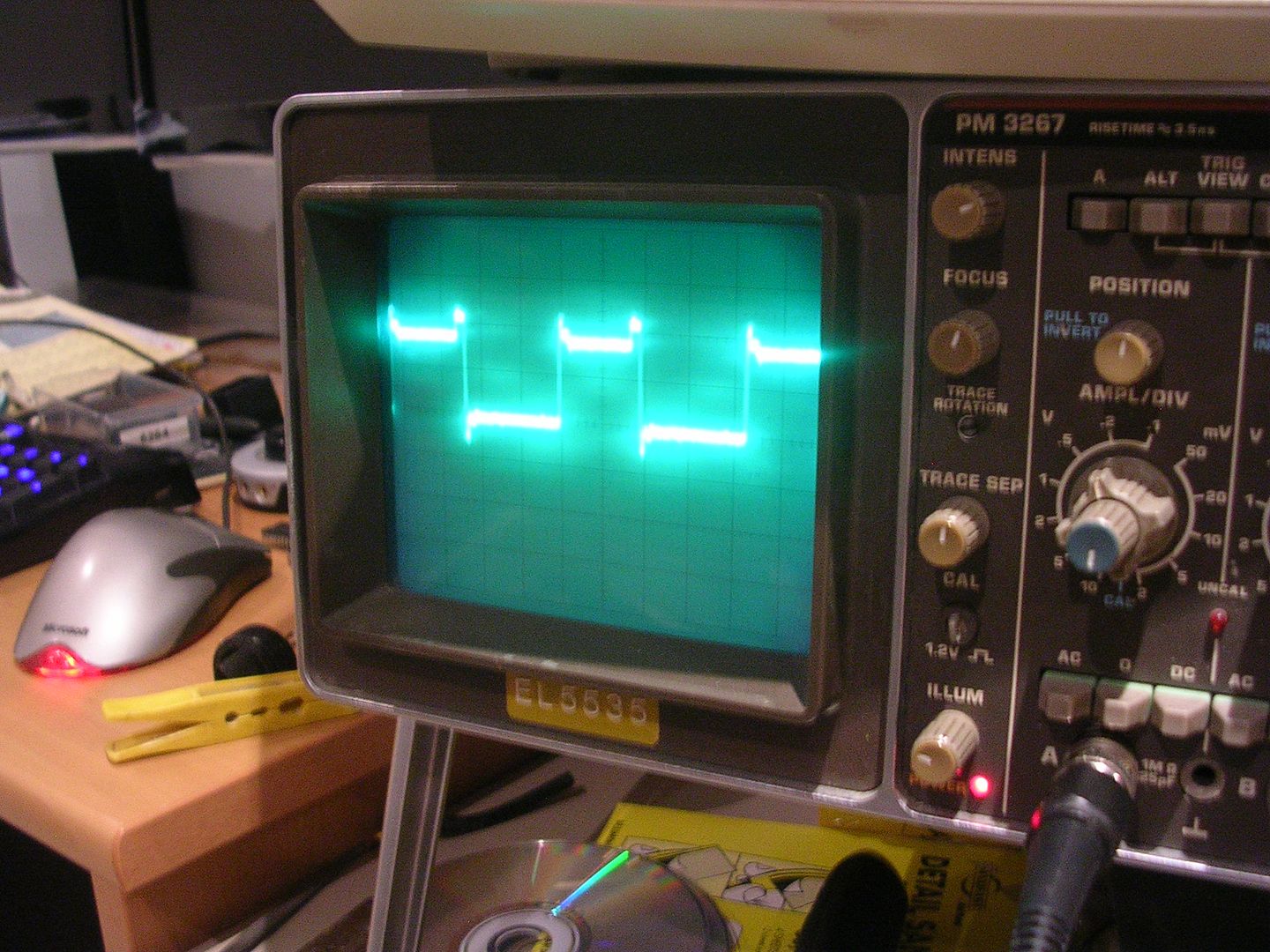
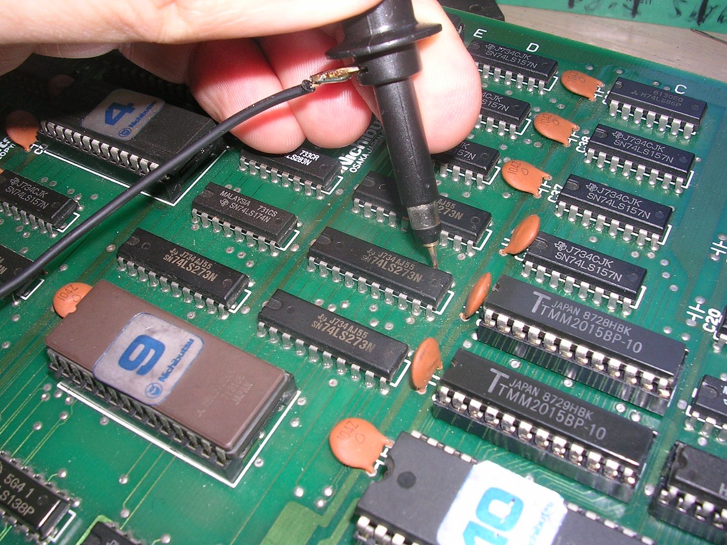
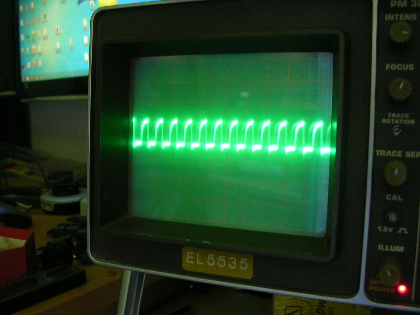
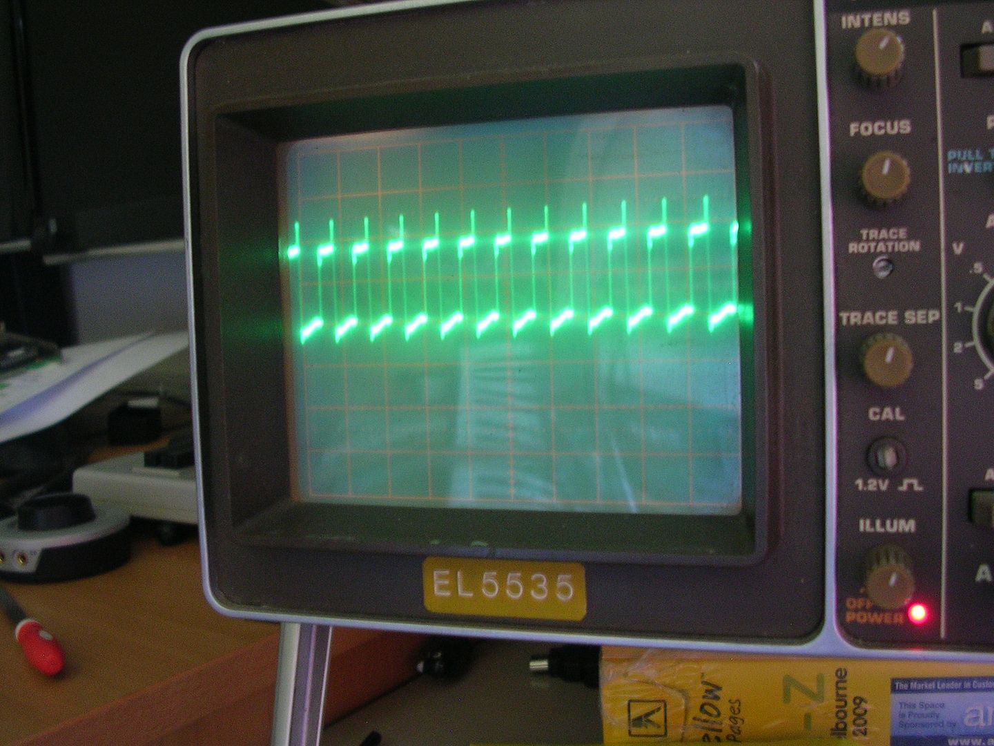
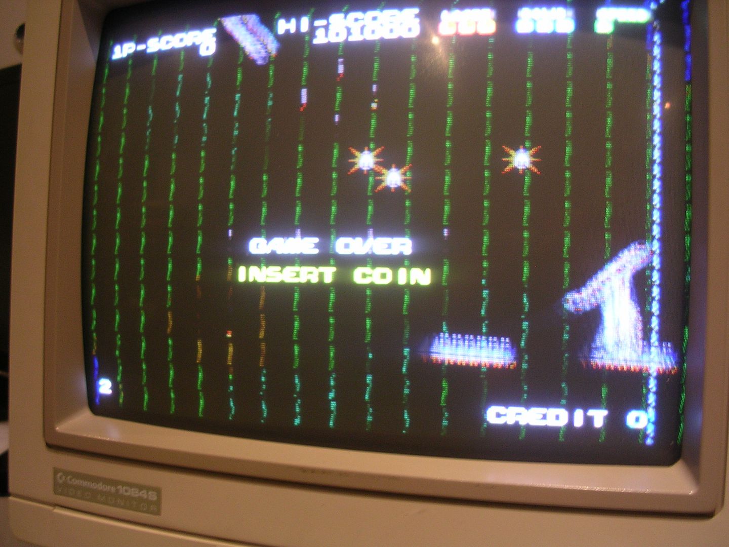
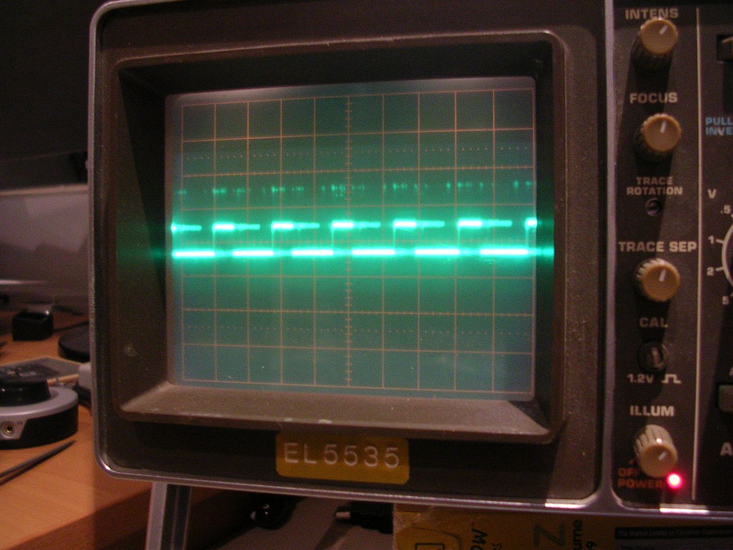
On some data IO pins the signal looked healthy(ish)...
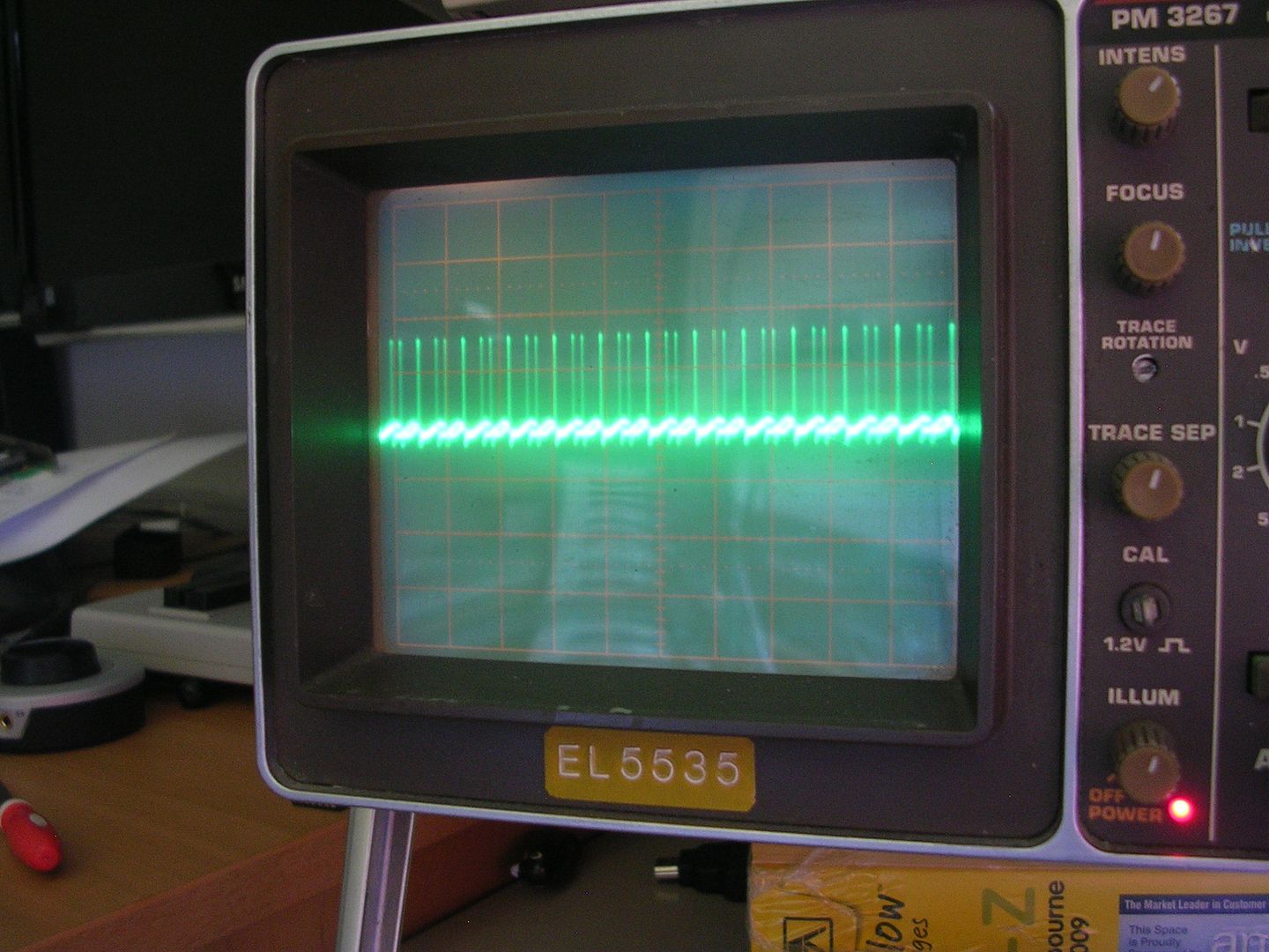
...but on others there was just a ragged mess...
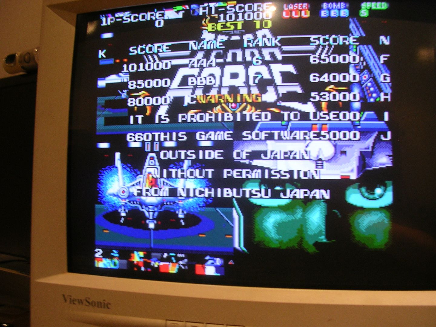
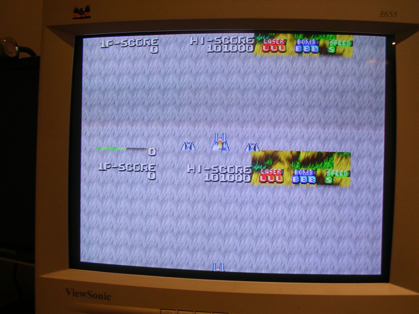
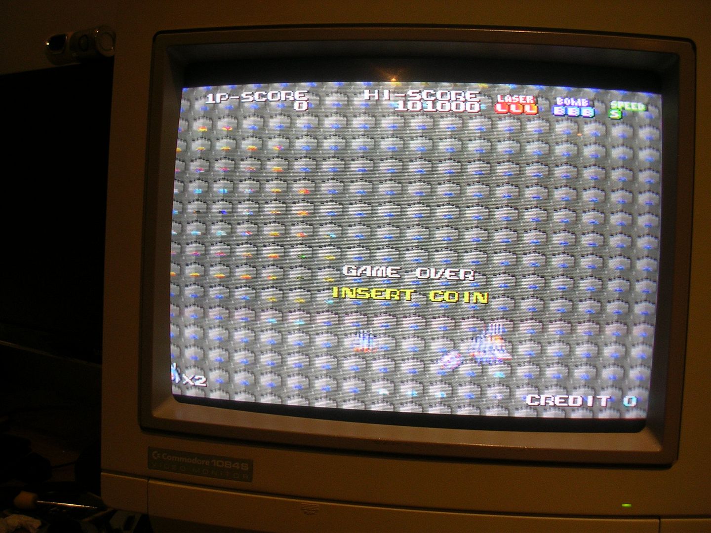
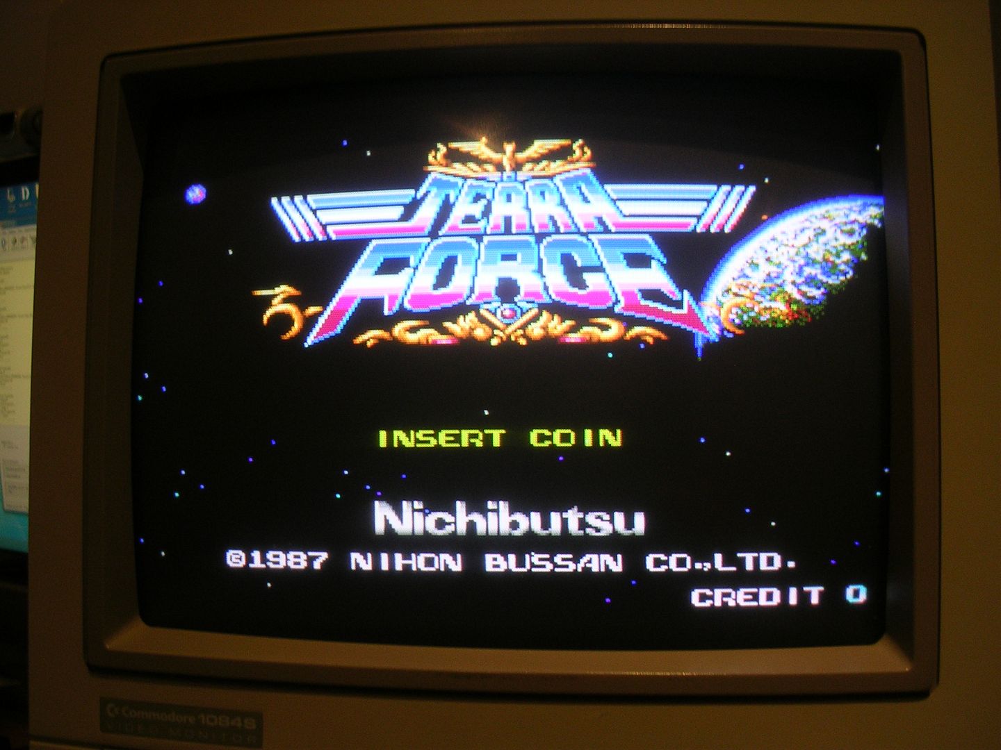
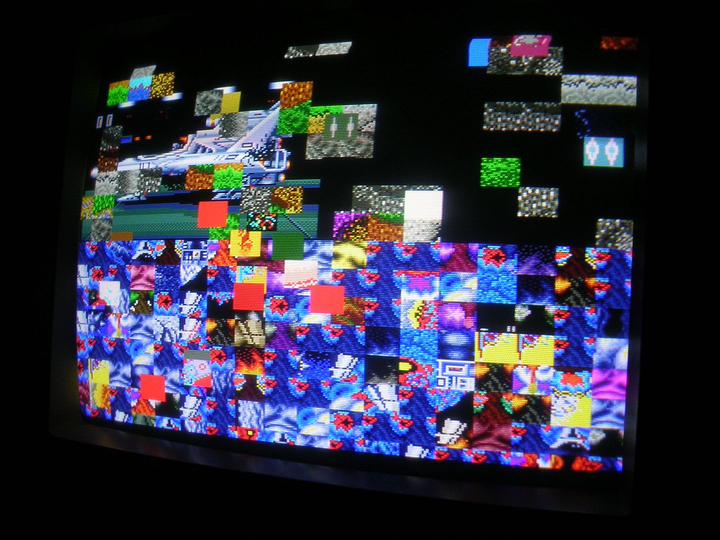
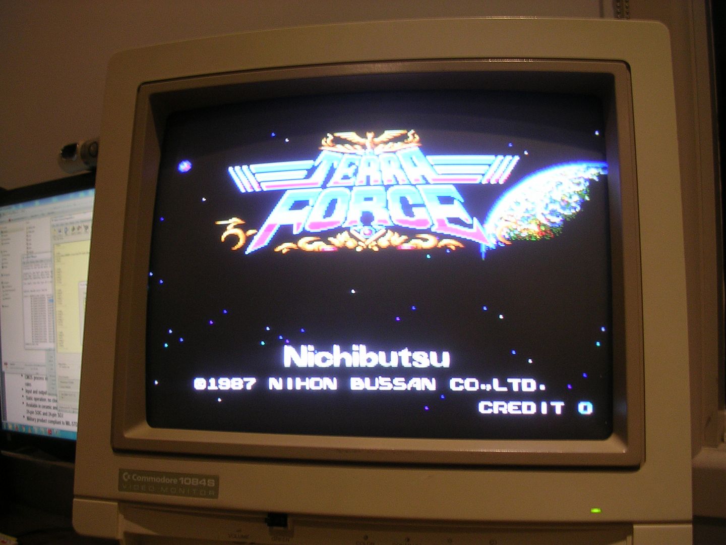
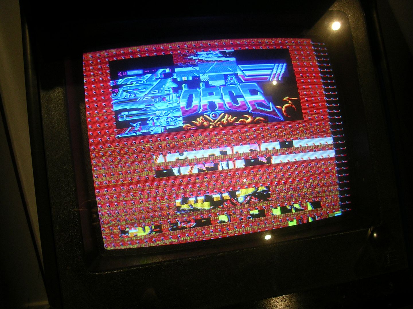
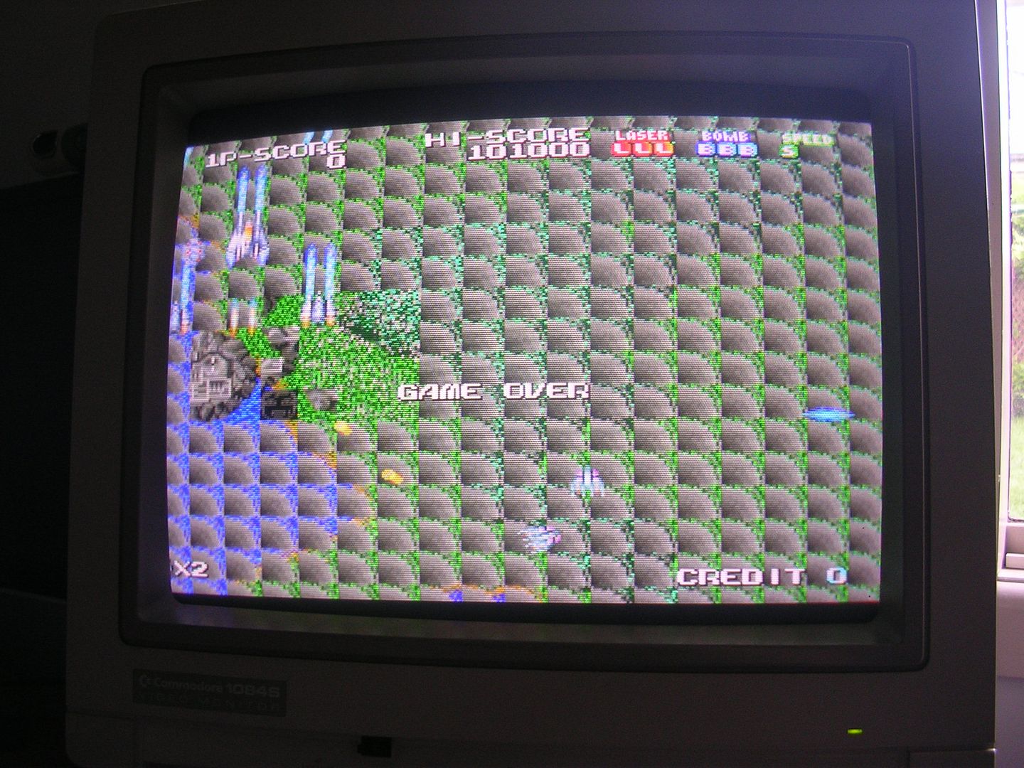
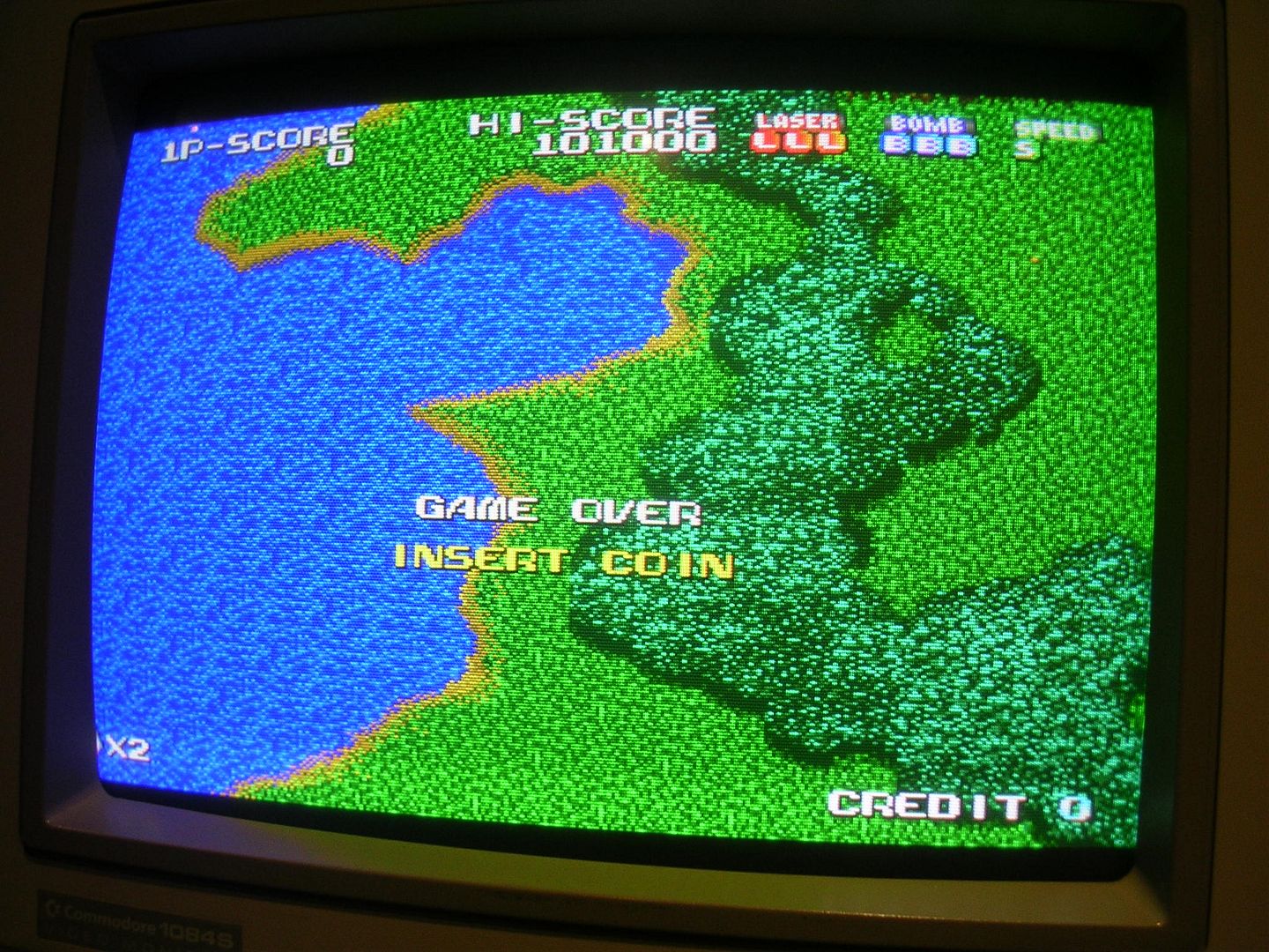
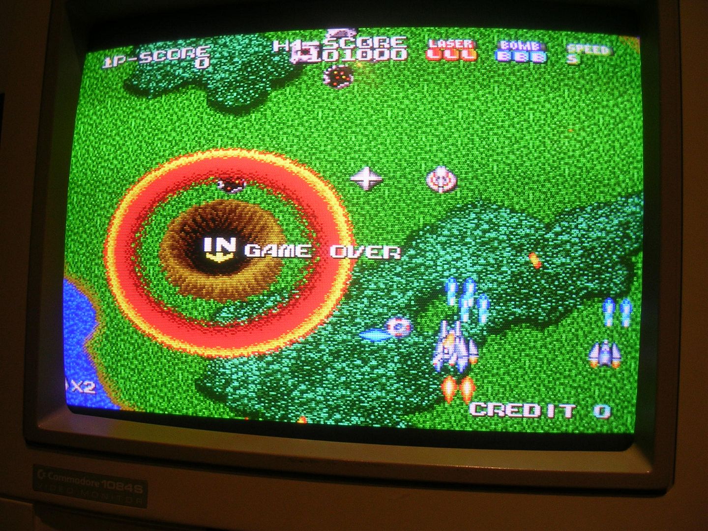
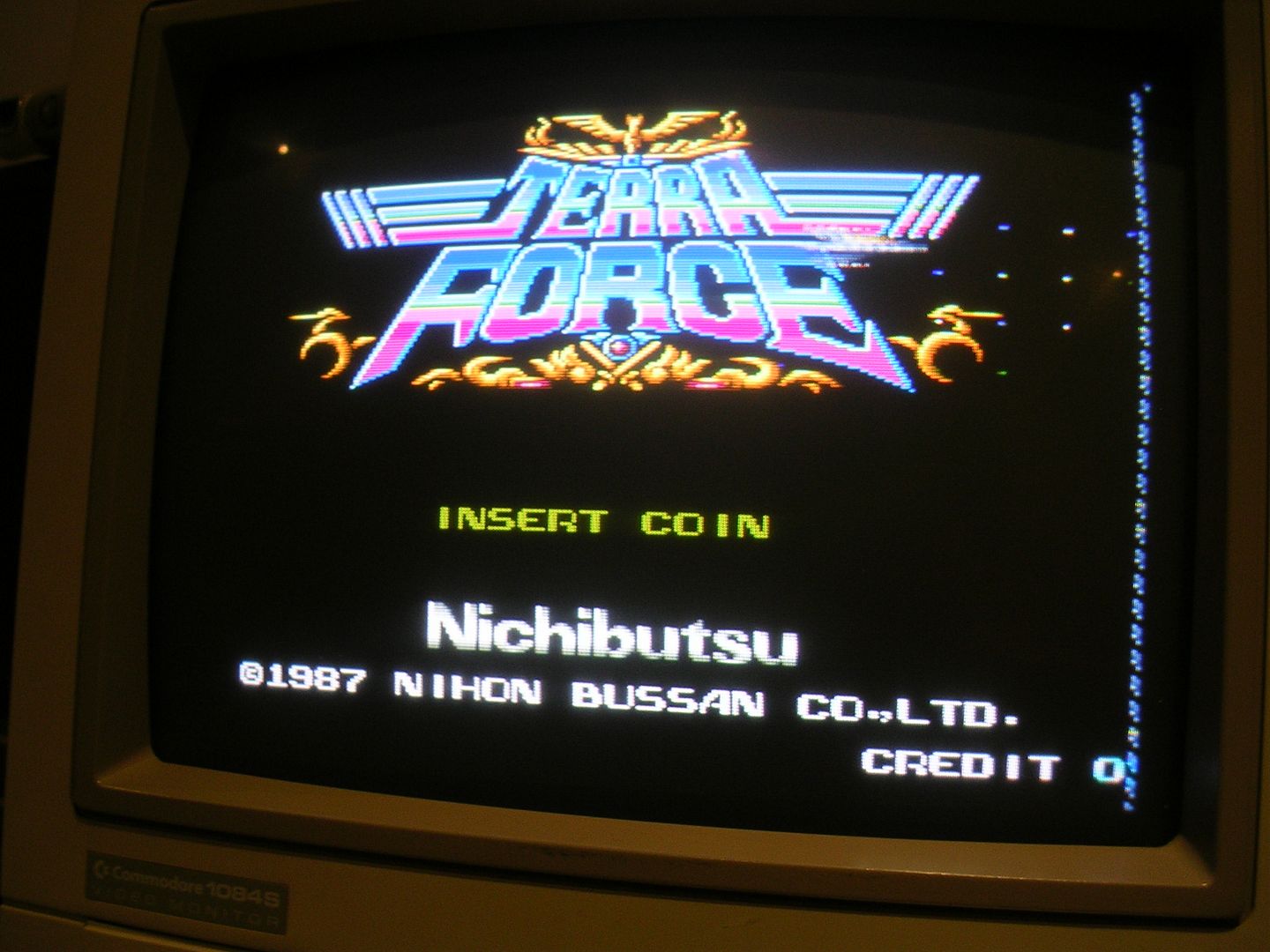
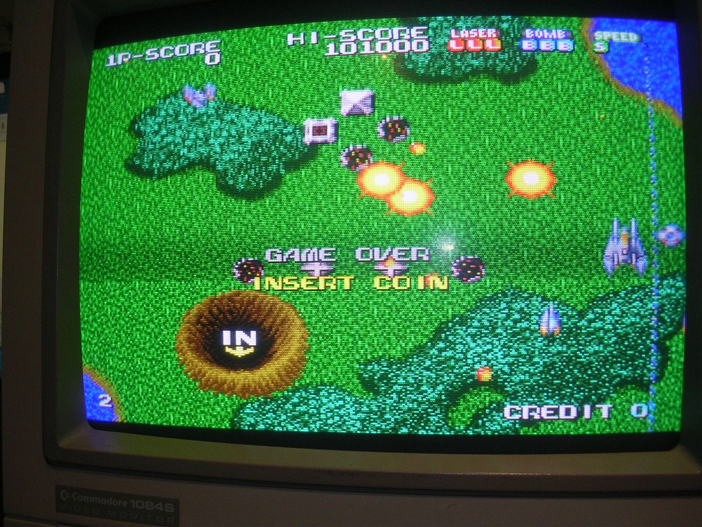
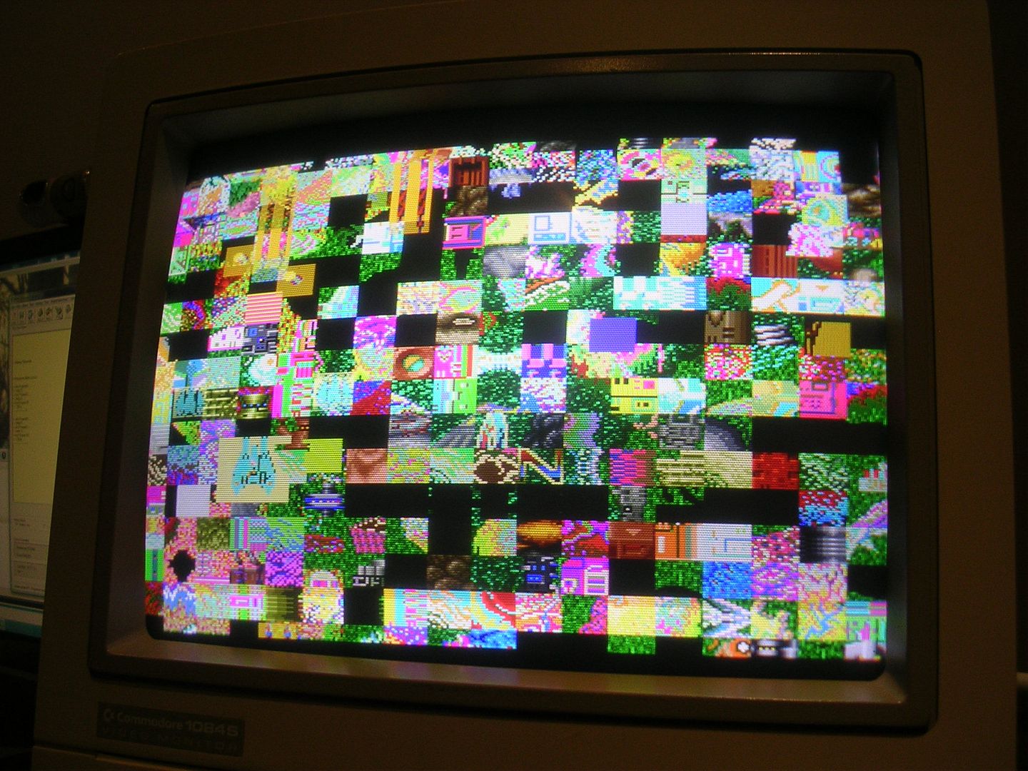
...and while poking around with the scope the screen did spring to life...
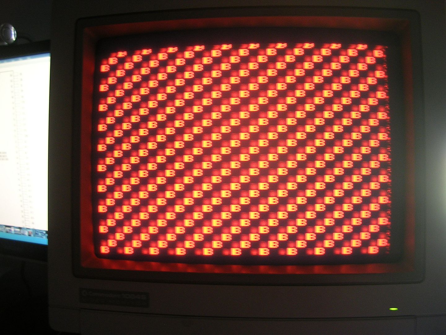
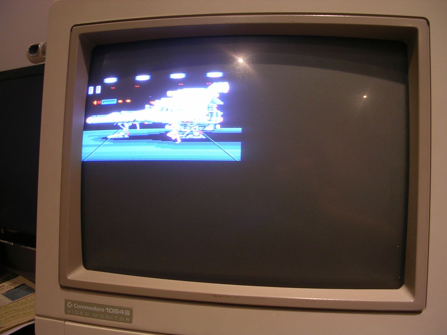
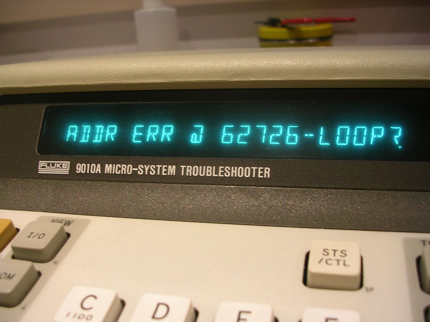
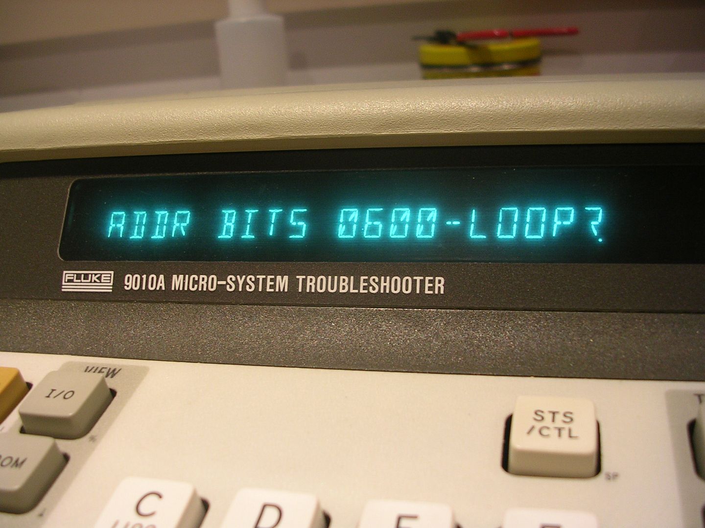
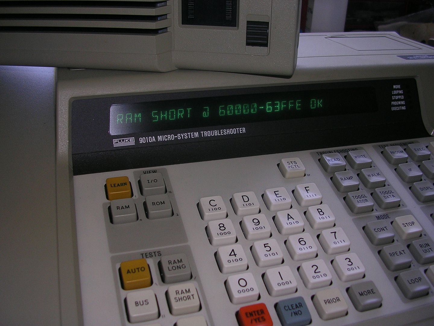
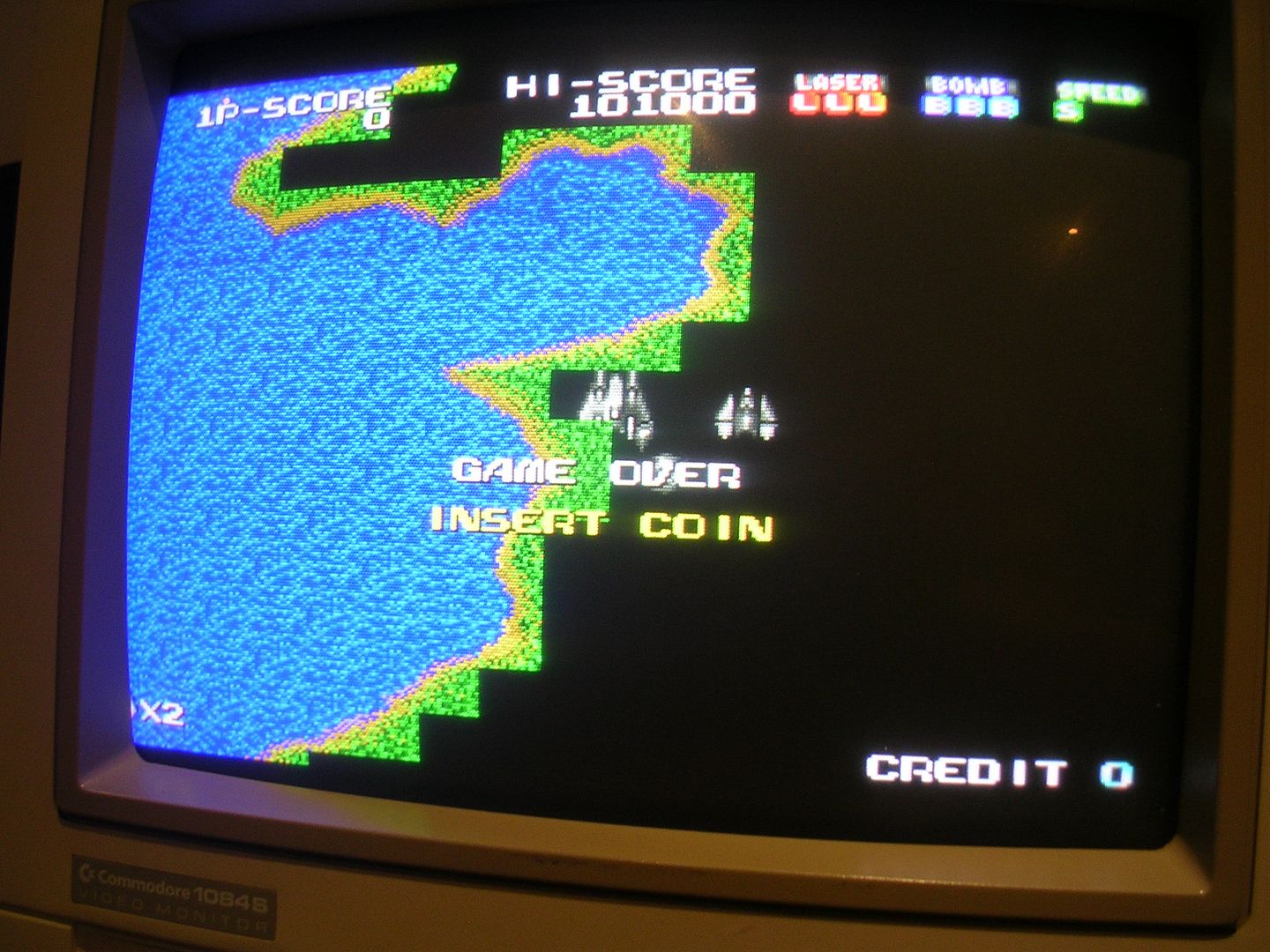
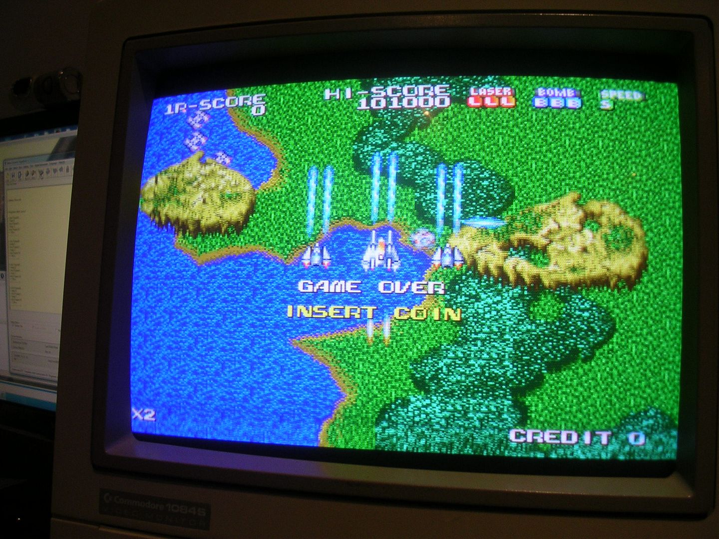
... and on reboot, I did briefly get this...
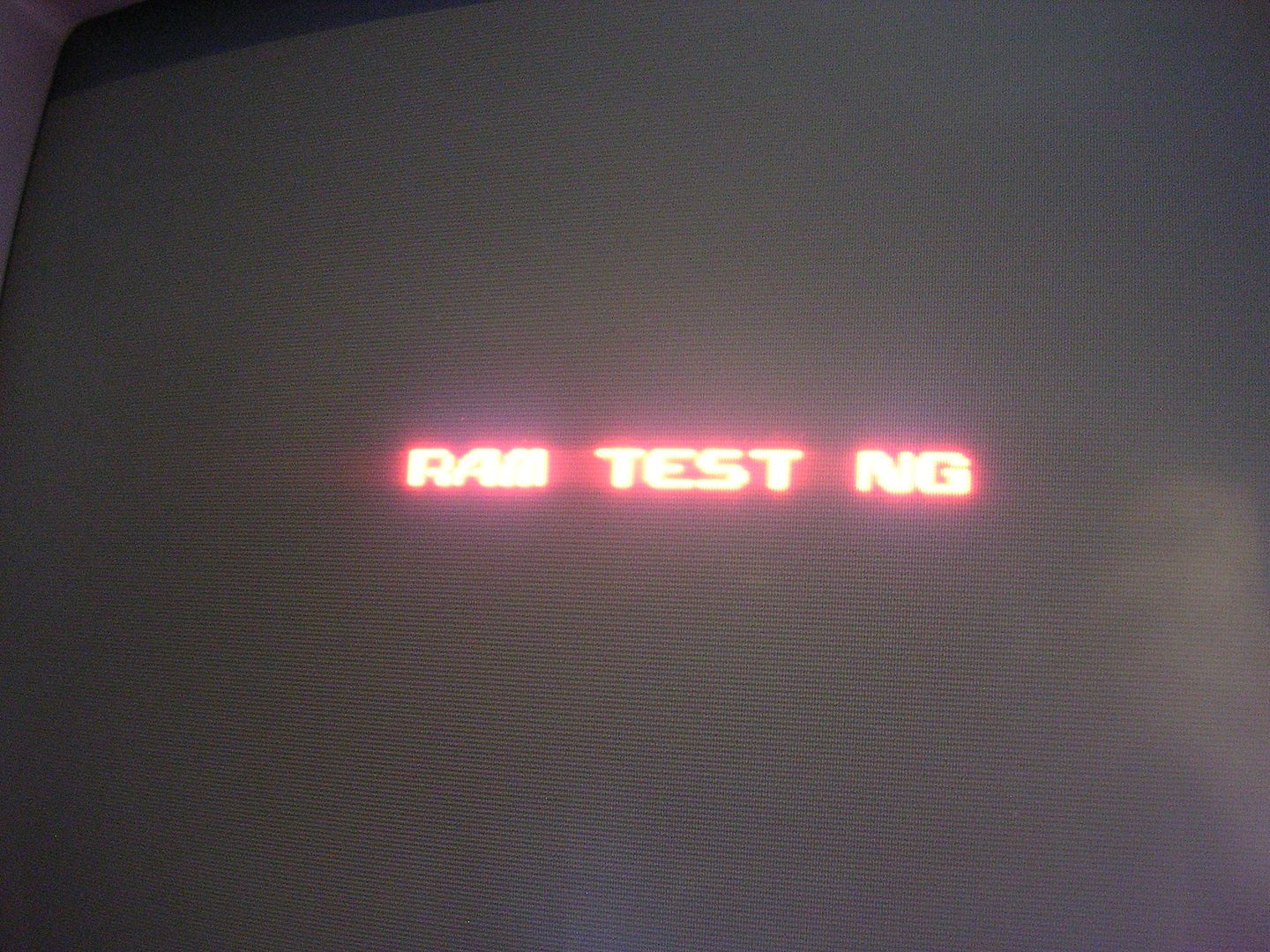
...once, before it returned to being dead.
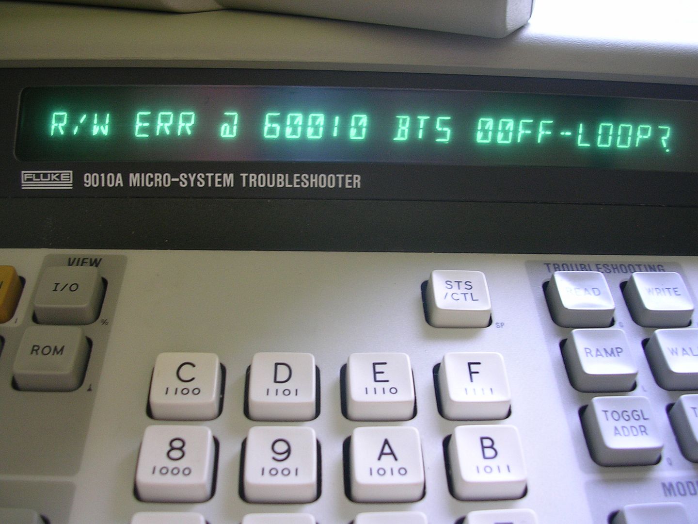
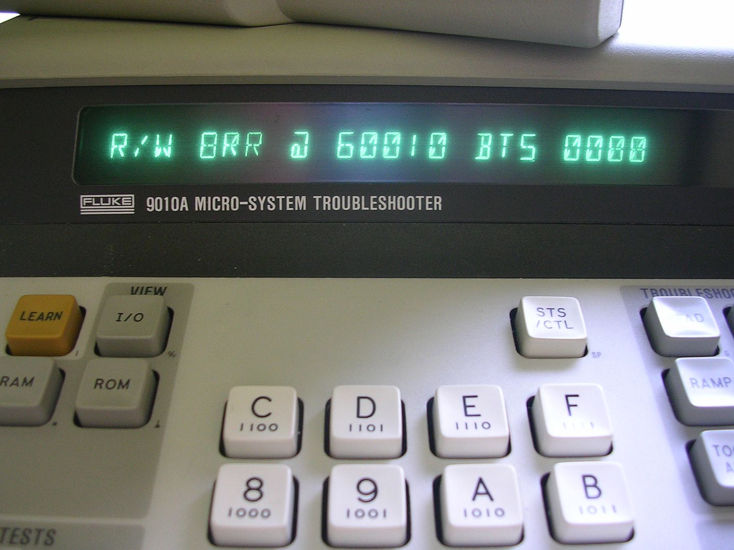
Which kinda suggests I was in the right area, the fact this board can barely even get this far isn't that surprising, the RAM/ROM check is itself a computer program running on the CPU, so if all the ROMs are dead then the test code isn't there, and if all the RAM is bad there is no space for the code to execute in. In this case the RAM is clearly almost totally dead.
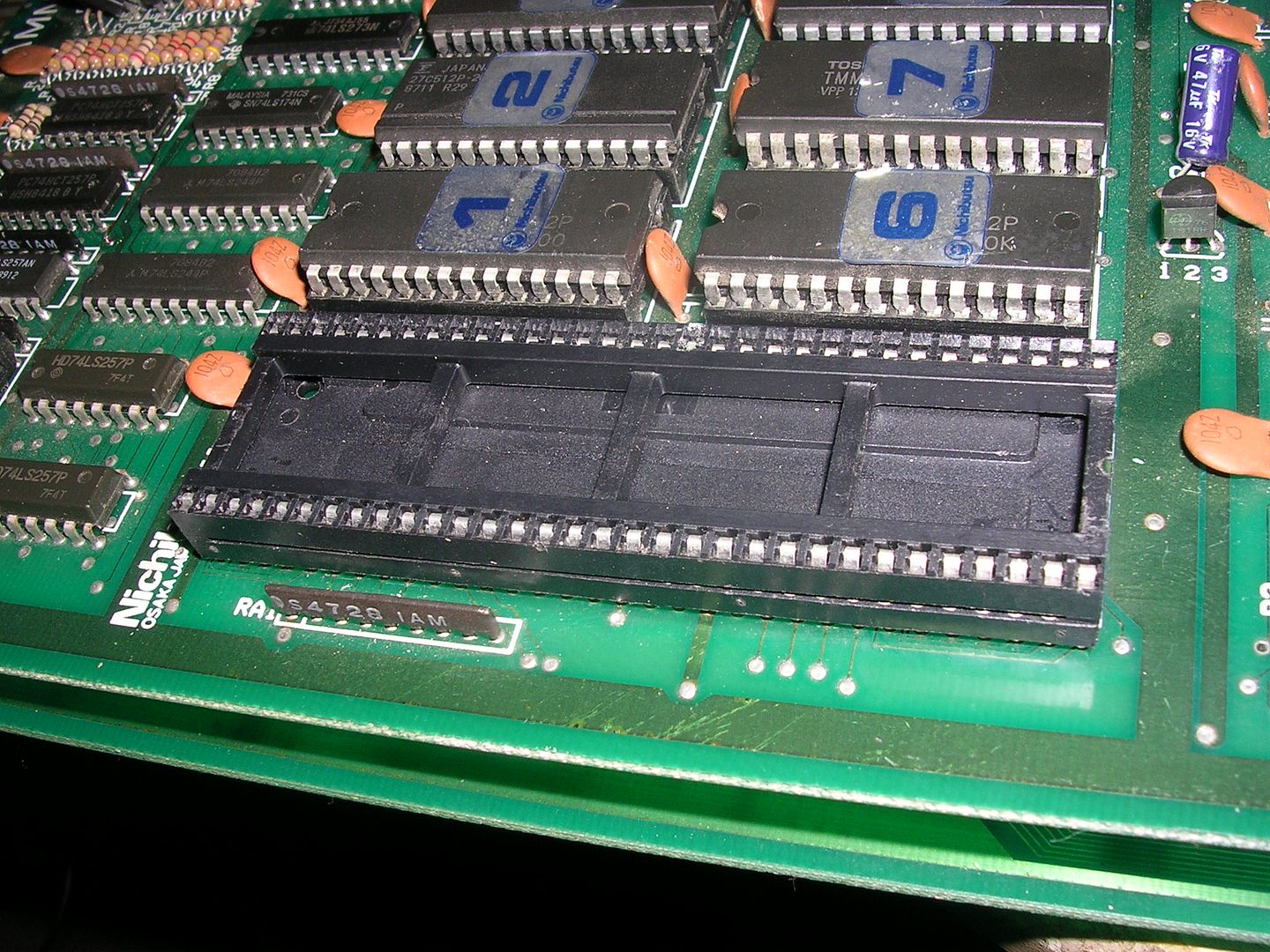
The desoldering gods were not on my side that day, normally I like to get a chip off intact so I can test it off the board, but this was hard going, so I cut them off and removed the legs individually.
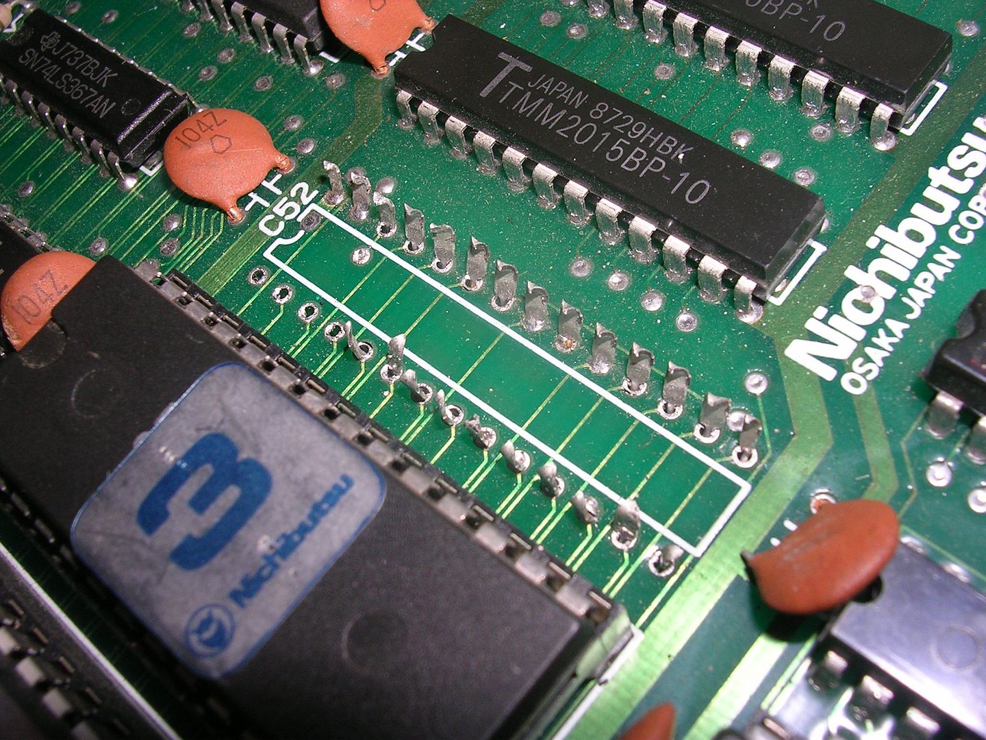

With two sockets fitted (about the only time I use sockets is for RAM and ROM) and two scrap board RAM ICs fitted I got.... a stone dead board again - the exact opposite of what was expecting.
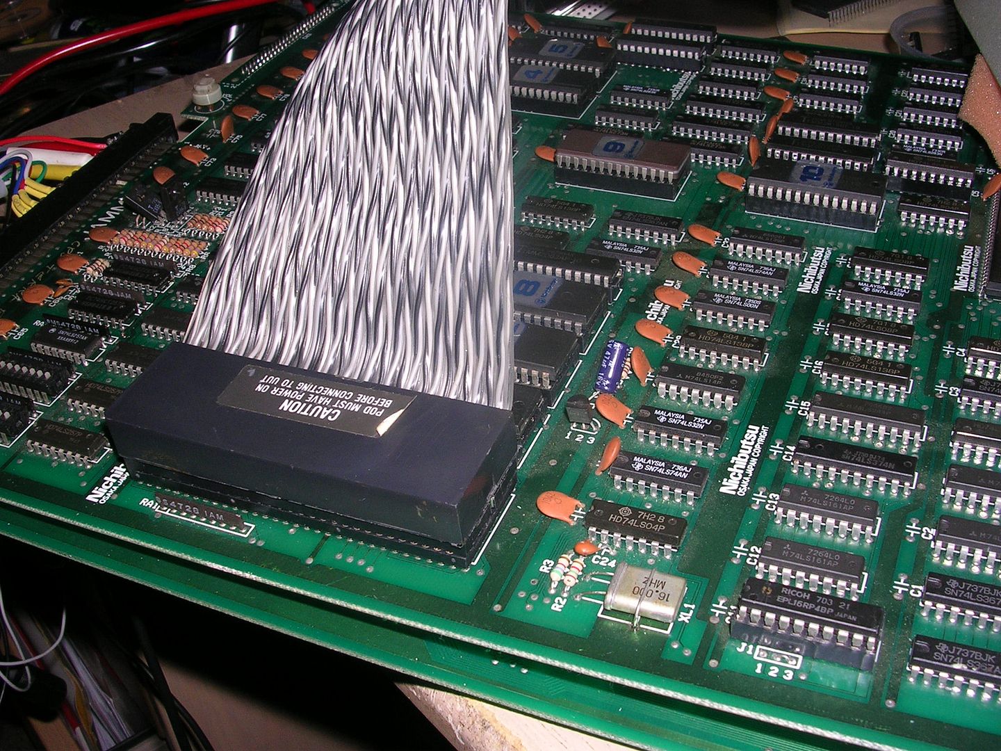
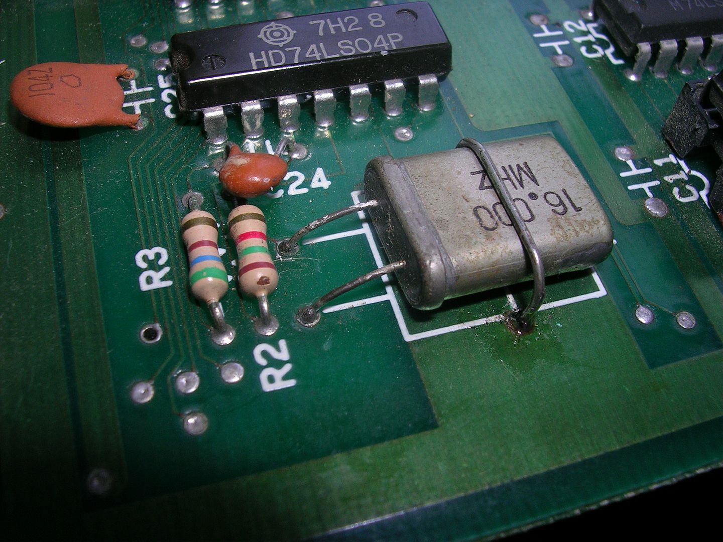
Going back to basics I found I now had no clock at all at the CPU, until I touched the 16Mhz crystal. It was only hanging on by one leg, the other had rusted through, it showed signs that someone had tried to solder it back on, trouble is you can't solder rust so it was barely making a connection.
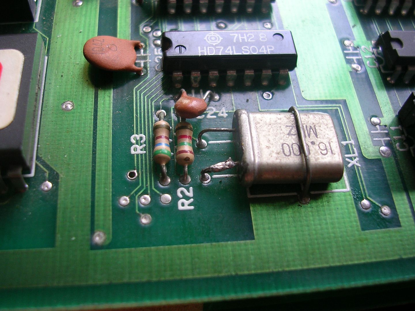
With no spare crystals of the right frequency I robbed the one from the other board set...
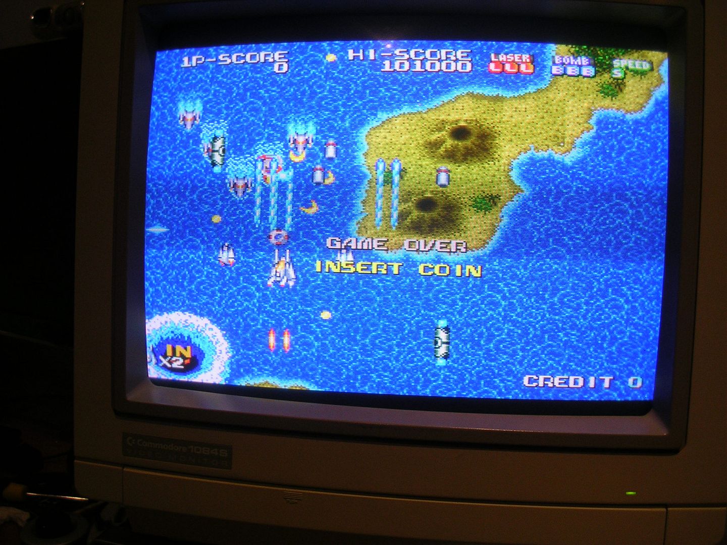
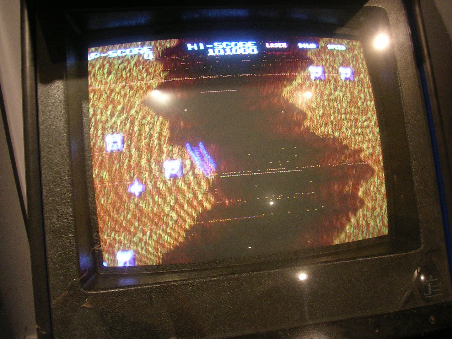
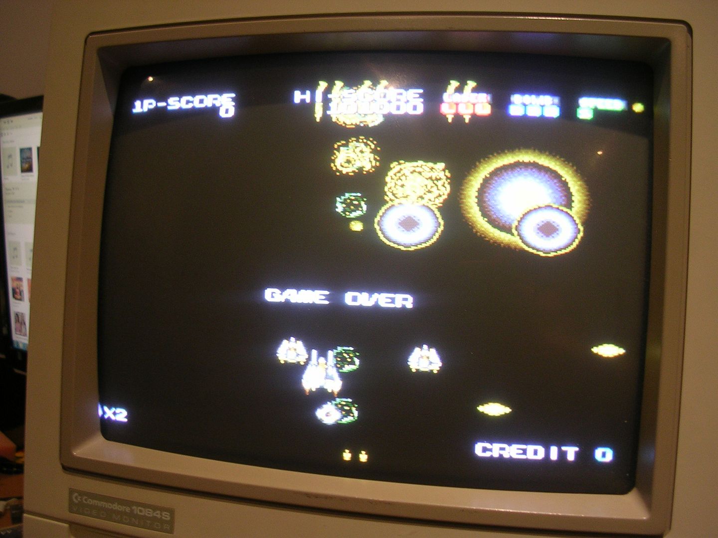
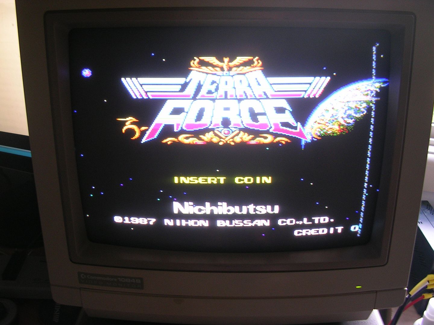
...and fired the board up.
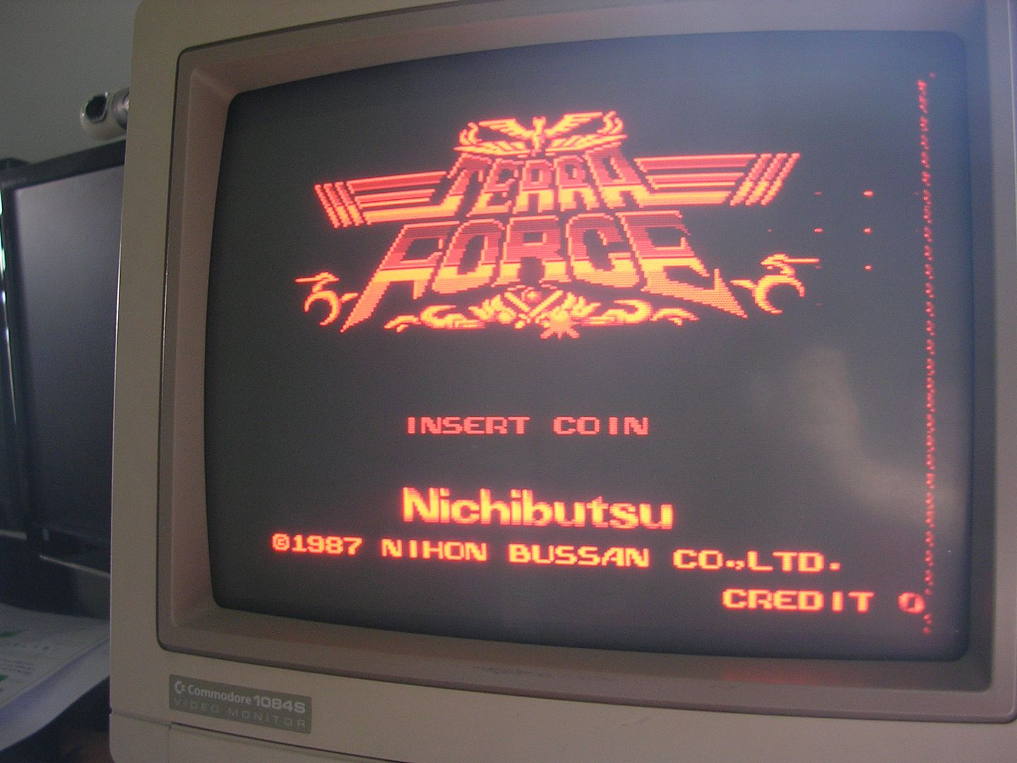
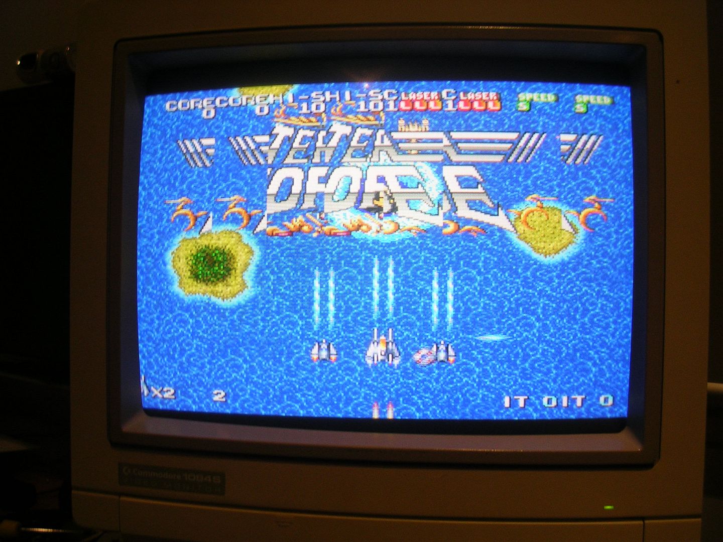
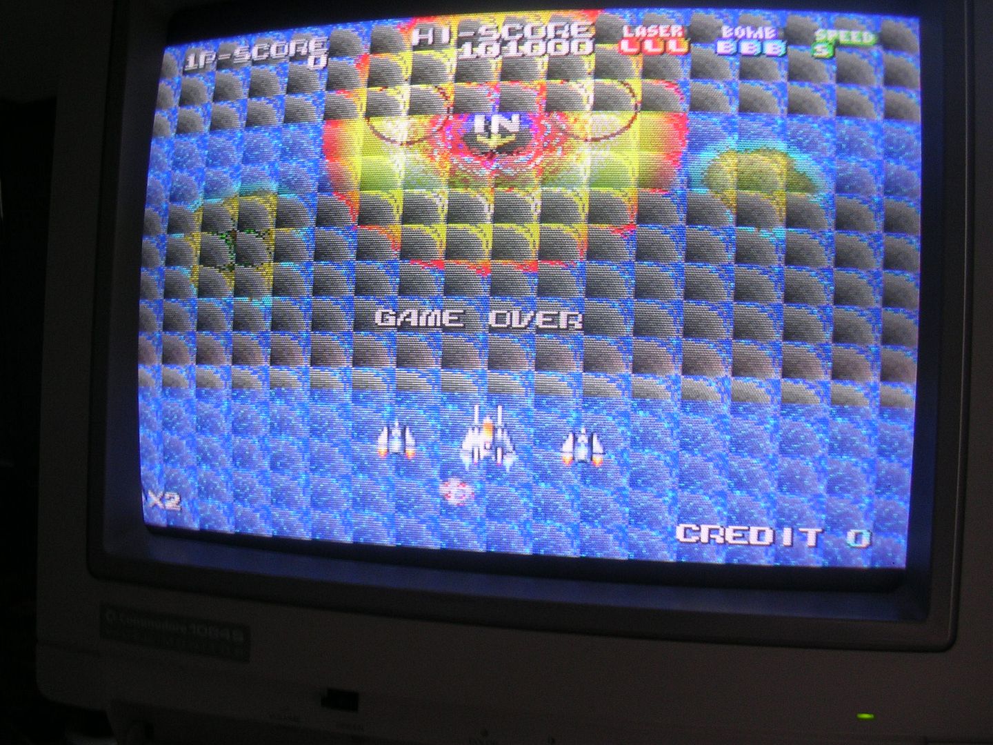
Progress, shame about the colours, and the background, and the sprites, oh and it crashed a lot, sometimes instantly, other times mid-way through the attract mode cycle, or after a few seconds if you tried to coin up.
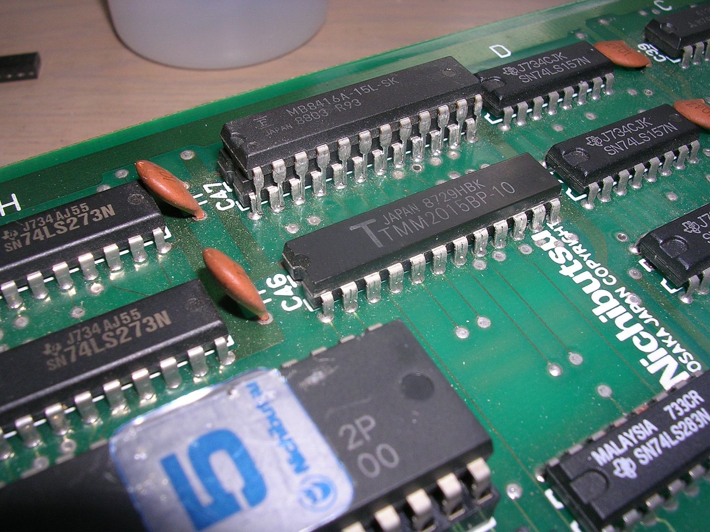
The colour fault was down to a totally dead TMM2015 SRAM chip at H8, one of the H8/H9 pair that form the colour RAM. This had activity on its address bus but its data pins were floating, which means you can piggy back another IC on top without any issues. It is as if the original chip isn't electrically there so it acts solely as an adapter. With a scrap TMM2015 chip from my stock piggy backed full colour was restored.
Not wanting to do any more desoldering I left the piggy back in place for later and moved on. The constant crashing was the main problem still, the graphics issues were secondary and were unlikely to be involved in the stability issues.
I had initially suspected bad contacts between the boards as being the cause for the lock ups, mainly because when it crashed it would not recover when the power was flipped off and back on, it would just power back up in the same wedged state.
After some poking around it turned out that pulling it apart and putting together just enforced enough of a delay between powering down and powering up for it to boot properly, it stopped me powering it back up too soon. This pointed towards the system RAM again as that is the only place the state could be stored temporarily, and as I had put a pair of mismatched junker SRAM chips it was possible they were not playing nicely together. Swapping in another combination, also junkers, cured the crashiness and also brought all the sprites back. These fly around the screen so rapidly its almost impossible to photograph them against a black background as the camera takes too long to focus on the bright spots.
It's unusual that the main system RAM has anything to do with the sprites on boards with separate graphics subsystems but this one seems to be an exception. It's lucky that the board was so crash-happy, if it had run fine just with mashed sprites I doubt I would have found my way back to the main system RAM as a suspect for that.
With every issue so far being SRAM related it was pretty easy to find the next issue, what turned out to be the foreground SRAM had a dead IC in the pair, and it responded to the piggybacking trick.
Lighting up the missing data lines.
Looks like progress to me, so it was desoldered and a socket fitted.
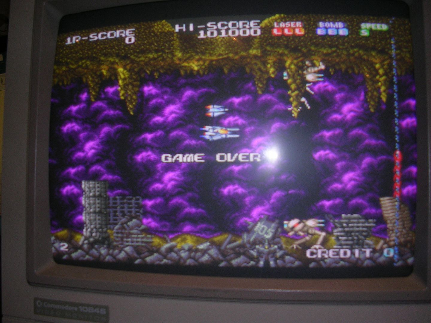
The one remaining issue was the overlaid band of pixels on the right hand side of the screen, my guess was that this part of the mangled the character layer as the text on the screen would glitch from time to time.
The culprit again was another pair of SRAM chips at E12 & E13...
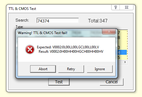
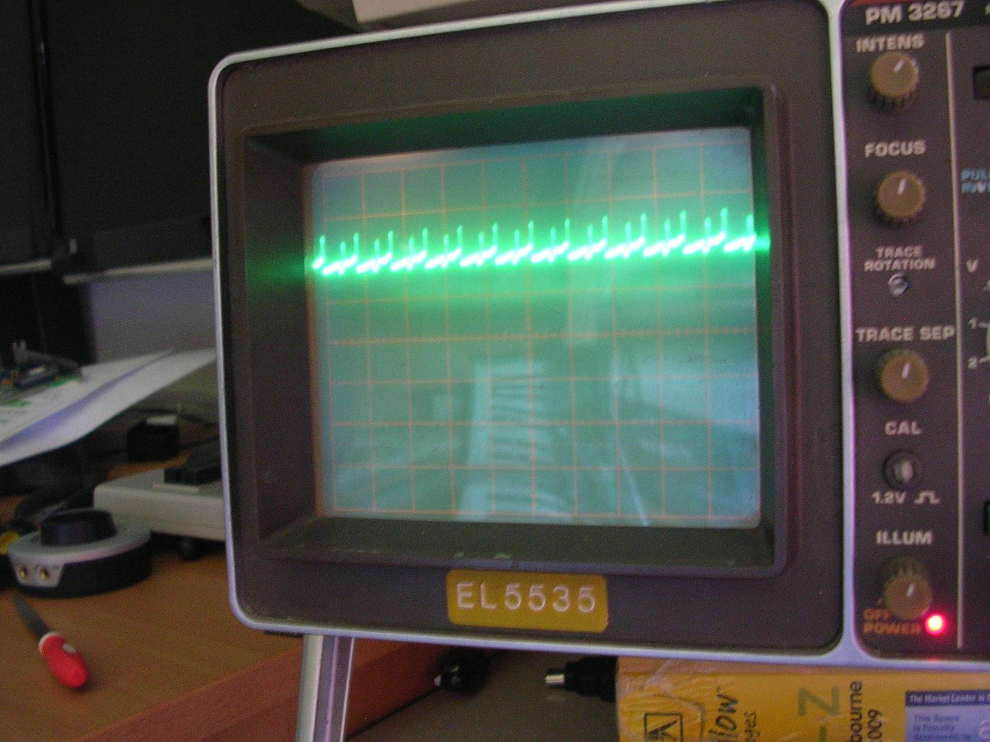
...with the scope showing bus contention on the data pins, basically one chip has lost the ability to keep quiet and let other chips on the bus talk, so the two chips fight each other, giving the half way data levels. It could also be the ROM but as I had a second board I could swap the ROM, the chances both ROMs would have faults on the /OE pin were unlikely so RAM it was, at least one of them was going to be bad.
I picked the wrong one of the pair to desolder first...
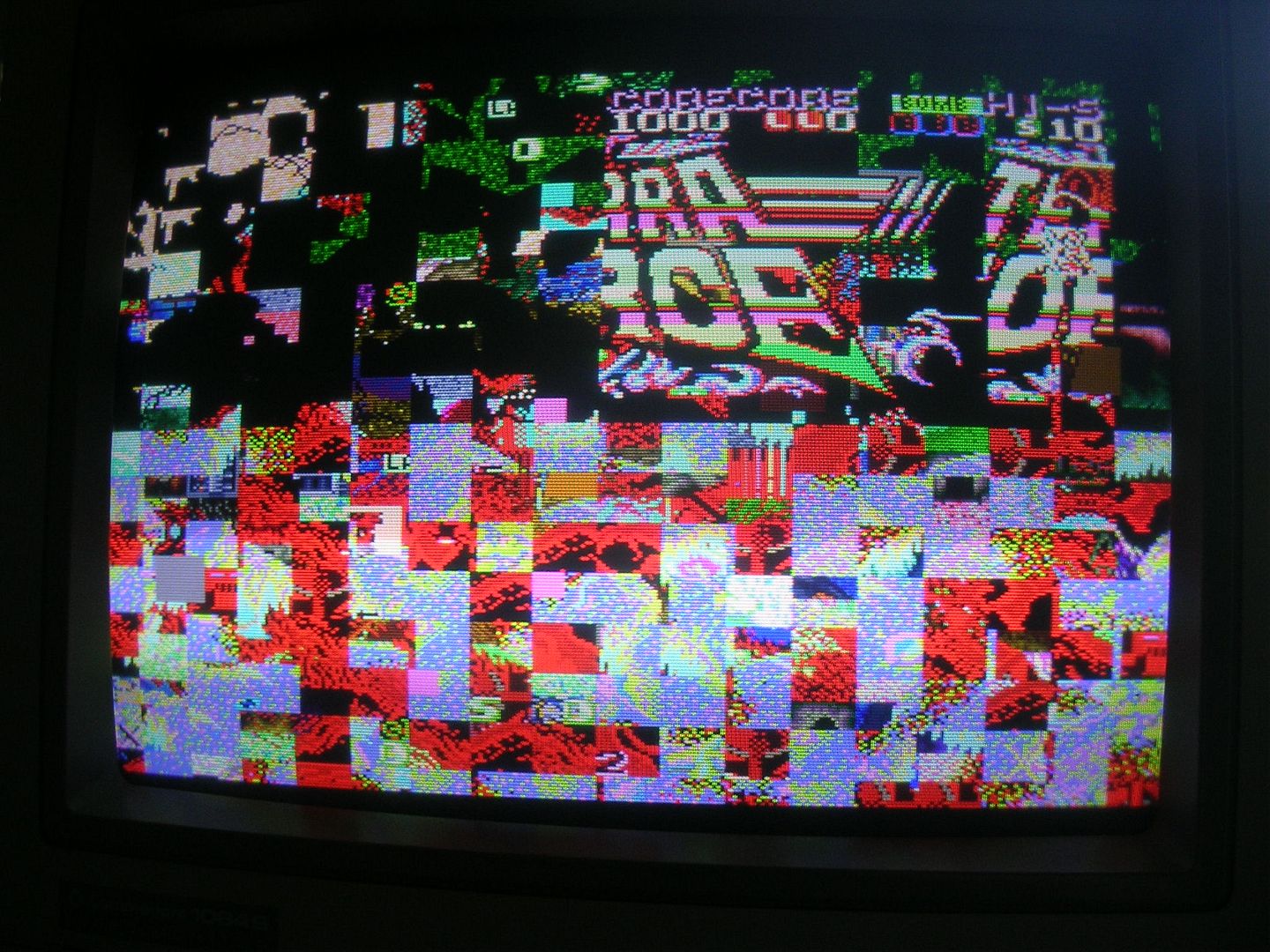
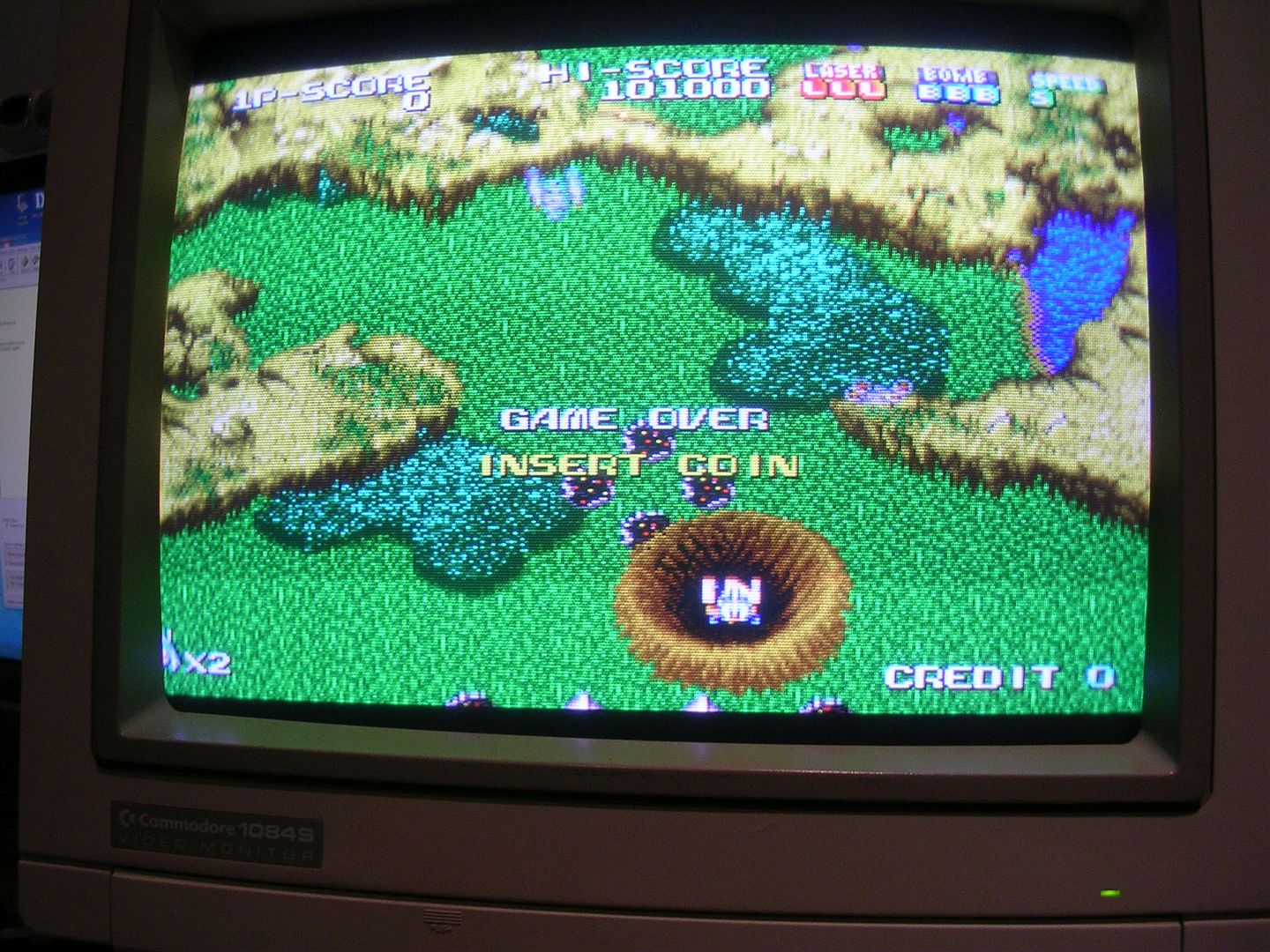
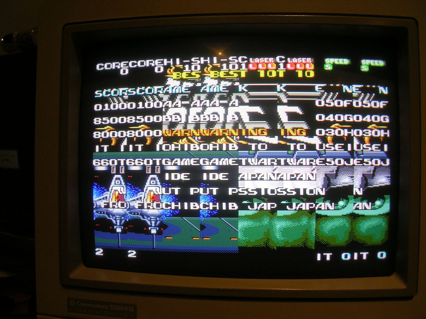
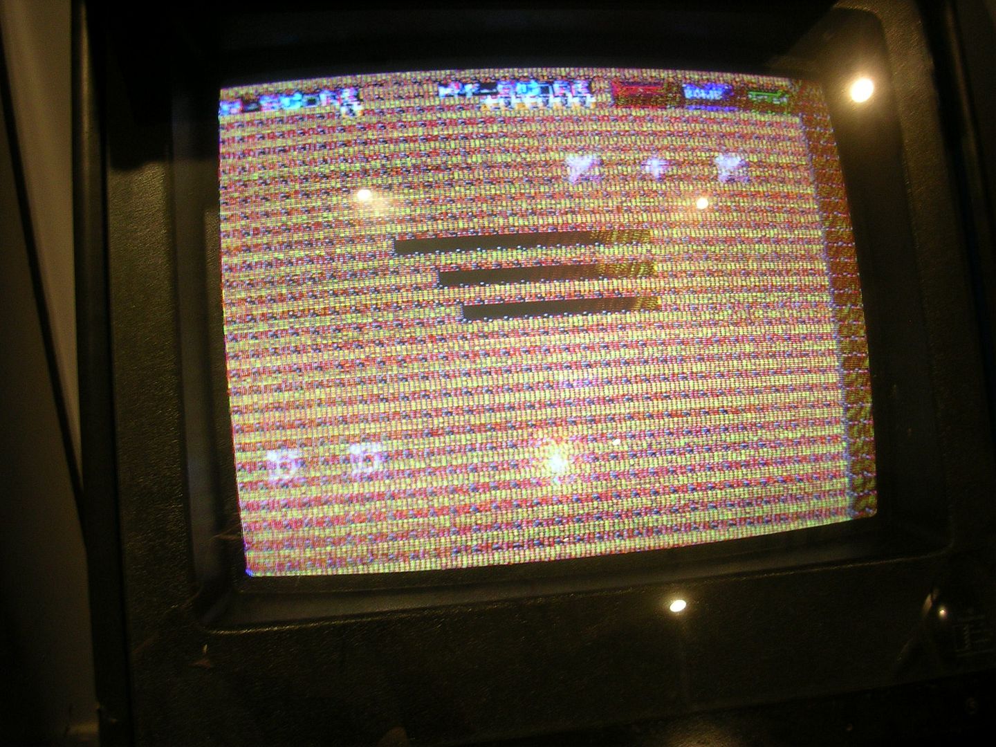
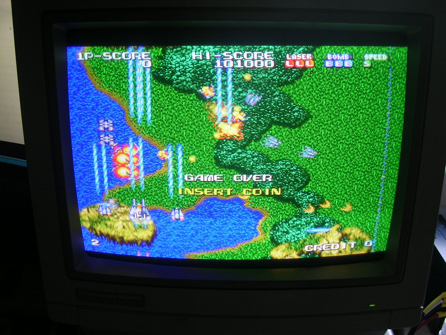
...with just the bad one left on the board I was greeted with this...
...with the game running in the background and a wall of crap in the character plane on top.
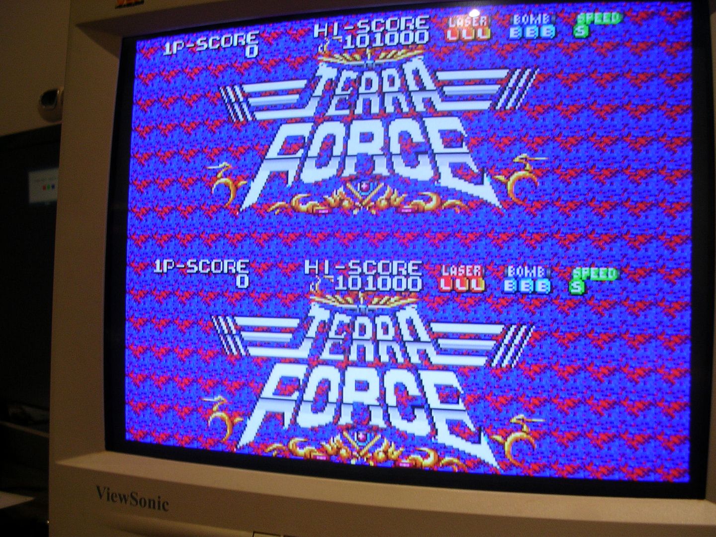
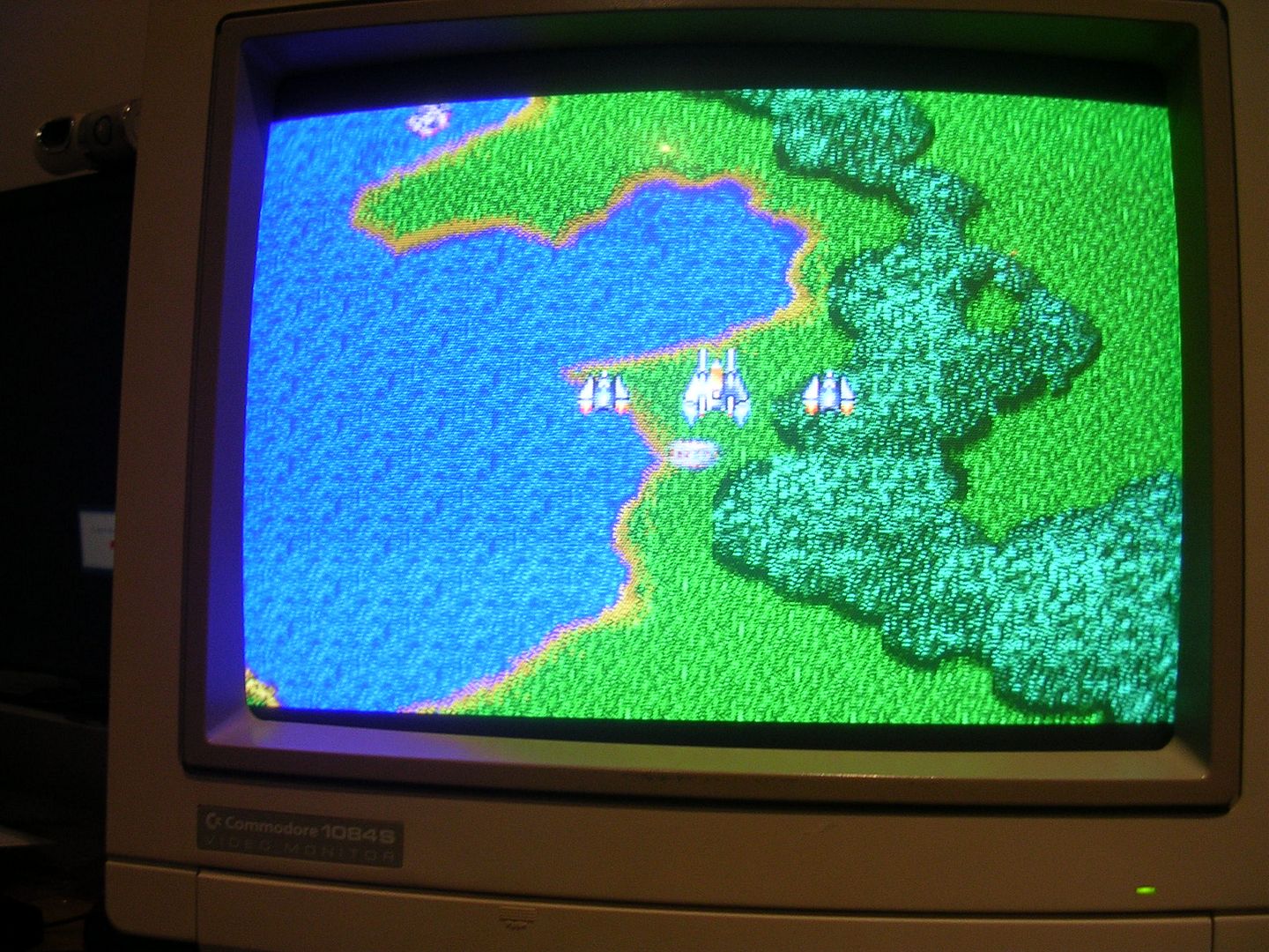
With the bad SRAM chip replaced I got this, graphical perfection!
All the controls worked and the game could be coined up and played, in silence, amplifier time.
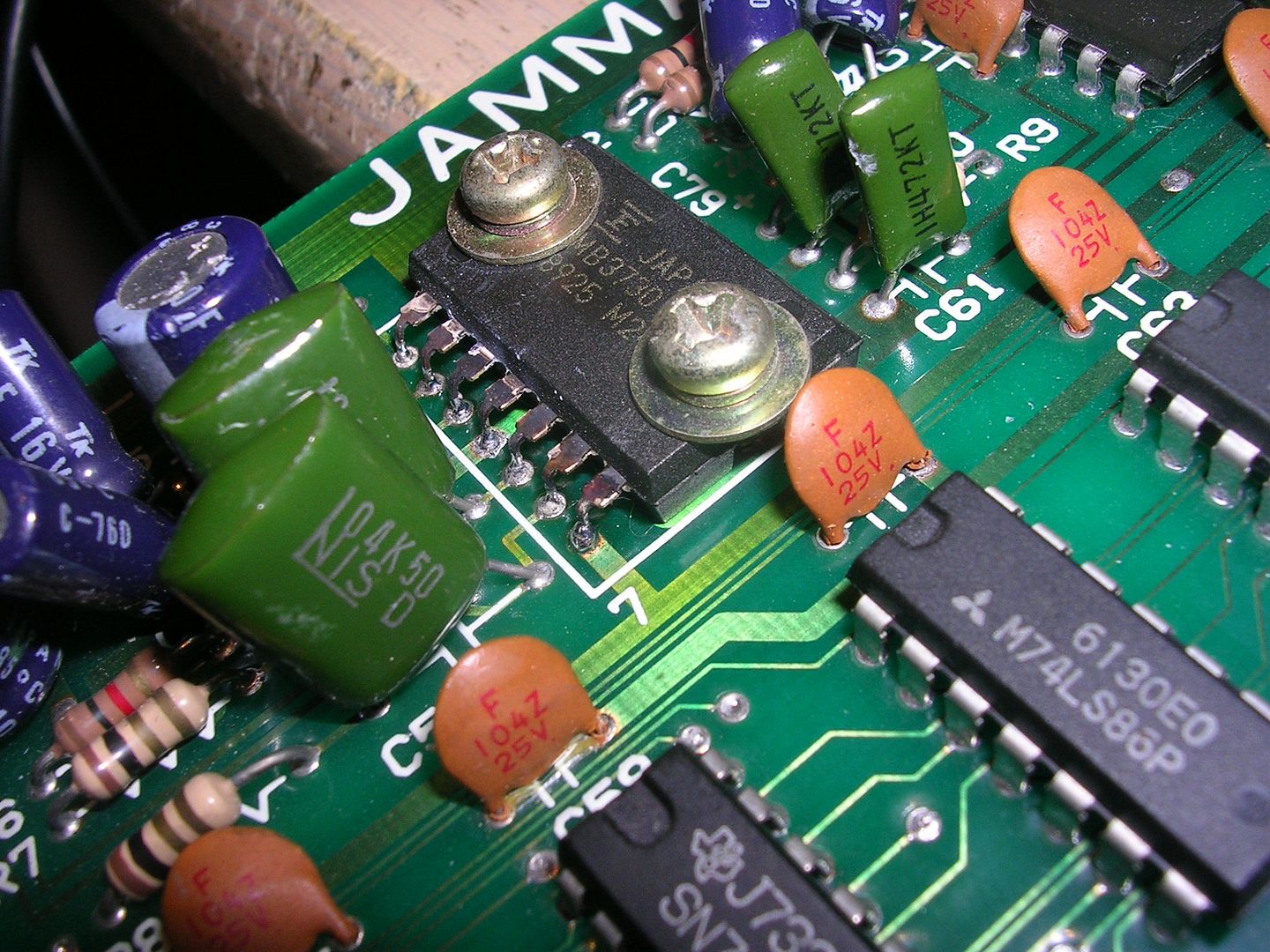
I had planned to pinch the amp chip from the other board set but the amp type was pretty common (handy to have a second board to check what it should be, there don't appear to be any schematics for this board out in the wild), so I found a replacement MB3730 on a scrap rusted out Midnight Resistance PCB.
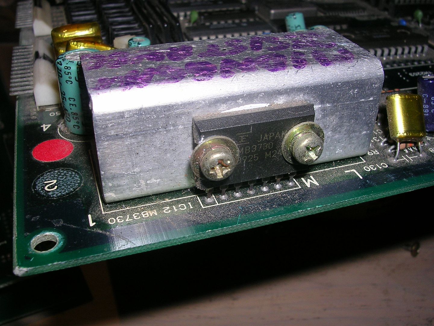
Whoever removed the original amplifier IC had done a very good job of desoldering the original...
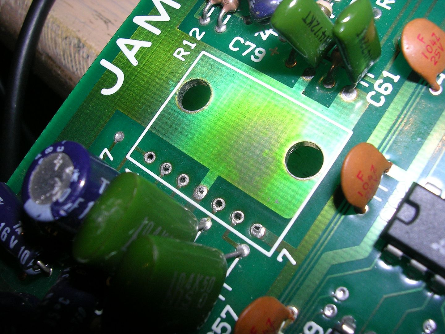
... so it was just a case of bending the legs, applying a drop of heatsink compoundt, bolting it down and soldering it in.
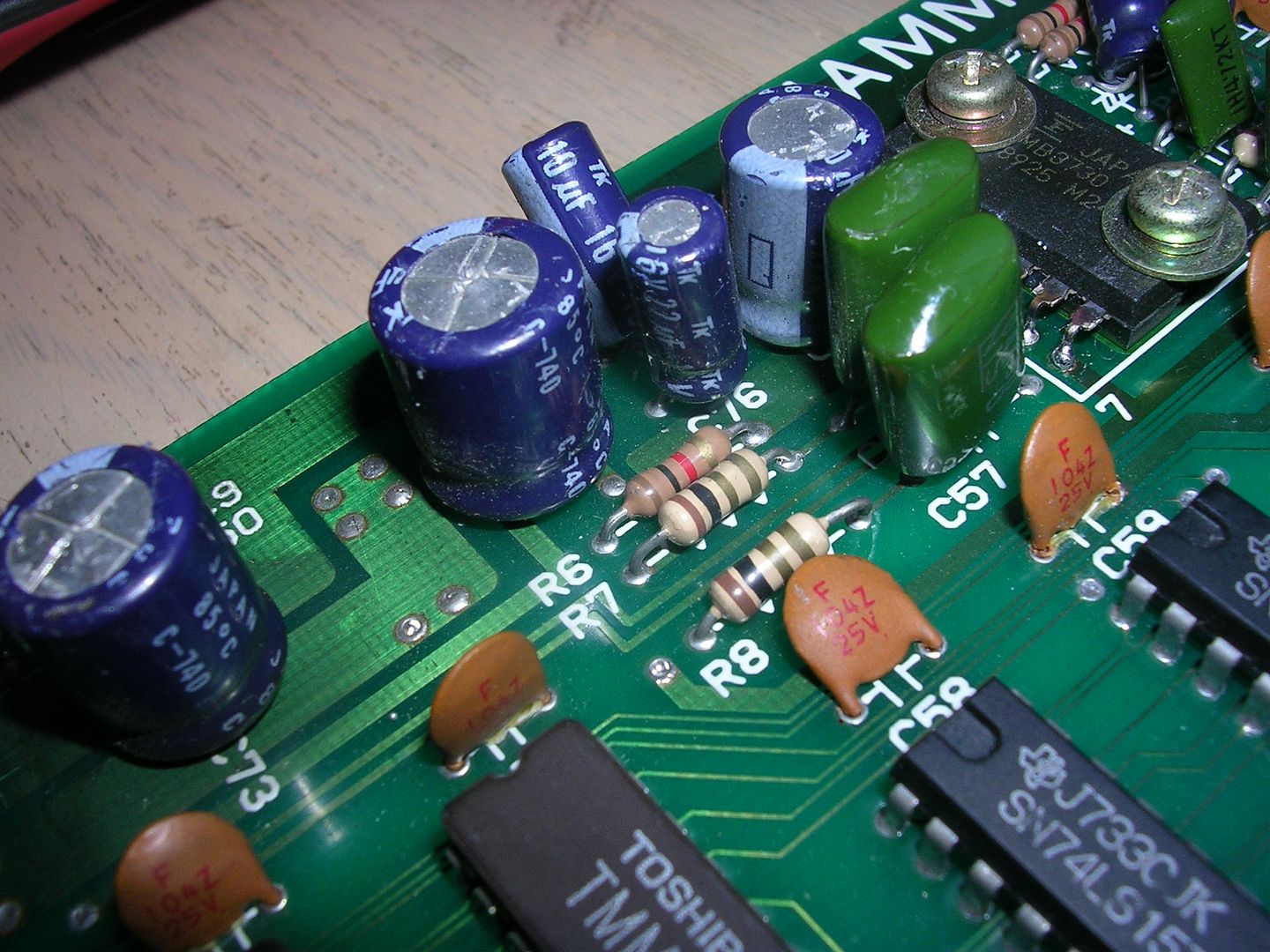
On power up there was still no sound, for about 30 seconds after which there was a massive pop in the speakers and the theme tune started to blast out. Whether the delay was the amplifier IC or the capacitors waking up after a long hibernation I can't tell, but it only did it once and the music and sound effects were fine, sadly the amplifier chip was not. It was getting roasting hot within 30 seconds of being powered on, which usually means it is oscillating. A voodoo blend of noise on the PSU, PCB layout, stray RF interference and component health can result in the amplifier oscillating, the first sign usually being a burning smell even though the audio may be fine. I had to assume that the PCB layout was correct and that it didn't do it from new, although it is possible that it was the cause of the original amplifier chip's demise. Logically the place to start were the capacitors, specifically the 470uF one between 12V and ground which is there to clean up the 12V power rail.
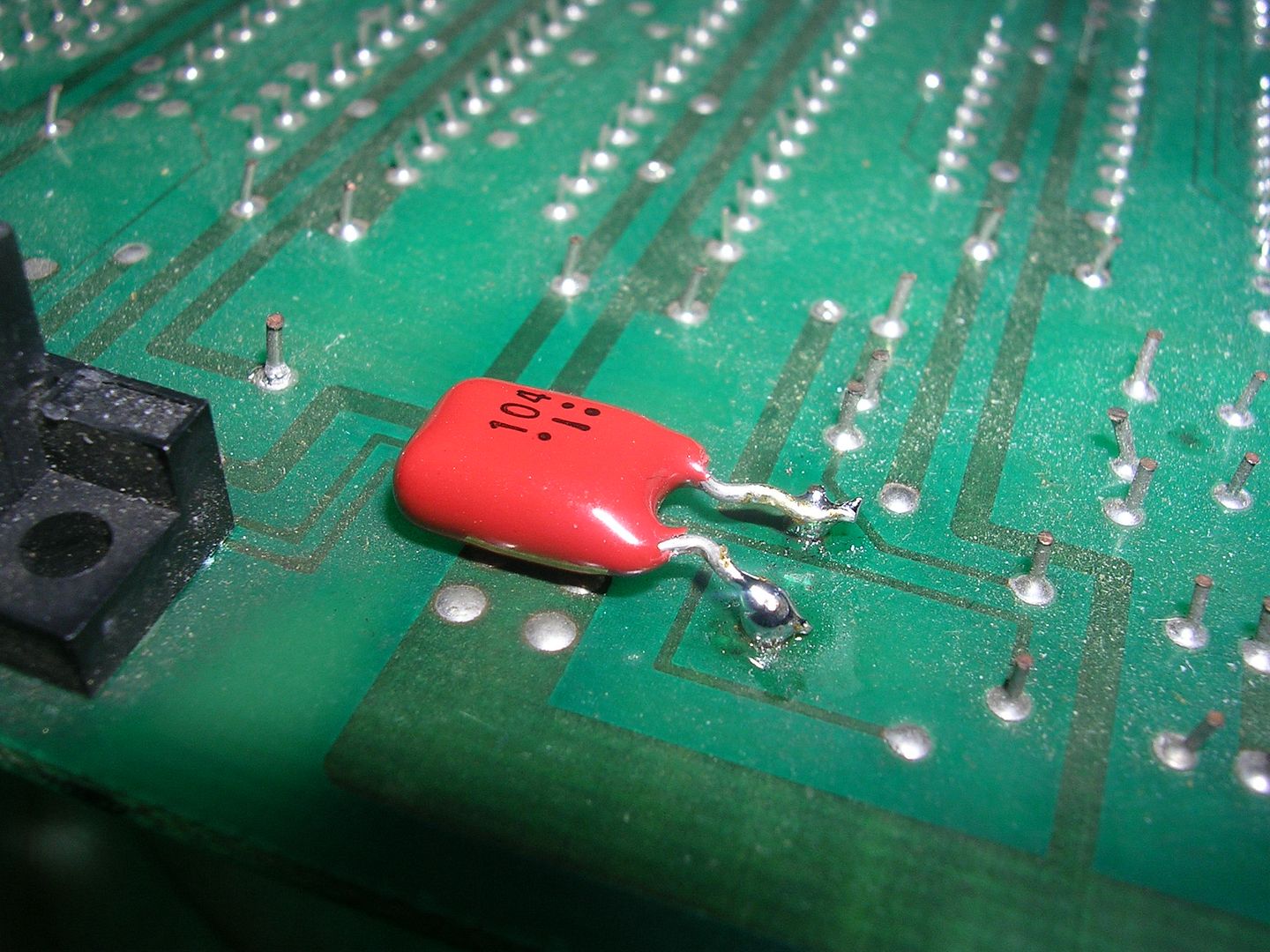
The ESR reading was about twice what a good cap should be, but ESR isnt major issue in this case. Anyway, a capacitor swap was easy enough, and it had no effect at all on the overheating problem. Decoupling for amplifiers power rails is usually achieved with a pair of capacitors, a very large electrolytic and a very small mylar capacitor. The large electrolytic provides power rail stability and mops up the low frequency noise, the small mylar mops up the high frequency noise. Digging up the datasheet for the MB3730 showed the recommended circuit for the IC with a 2200uF electrolytic and a 0.1uF mylar cap on the power rail. The PCB had no provision for the 0.1uF anywhere so I fitted one on the underside of the PCB across the 470uF capacitor.
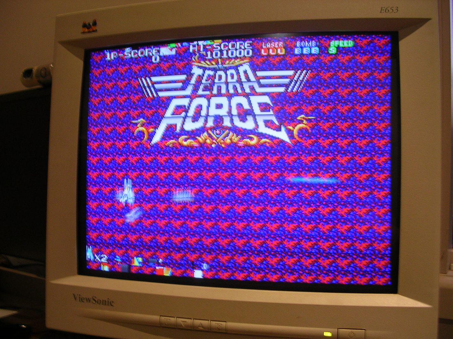
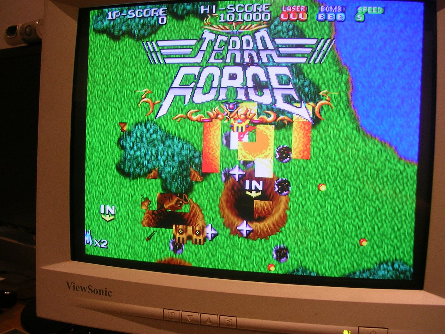
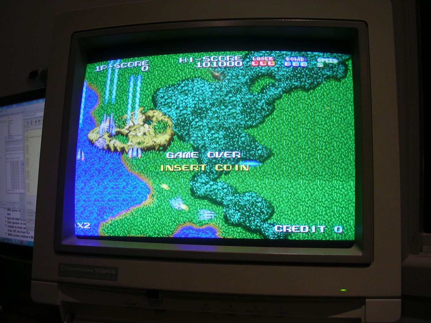
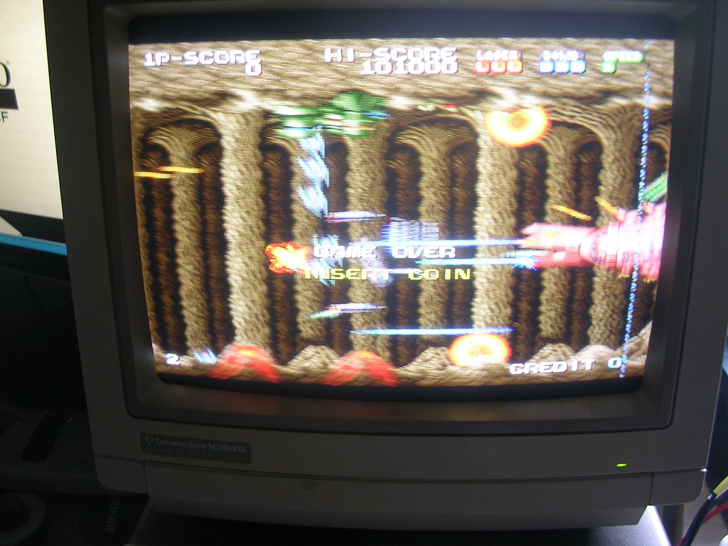
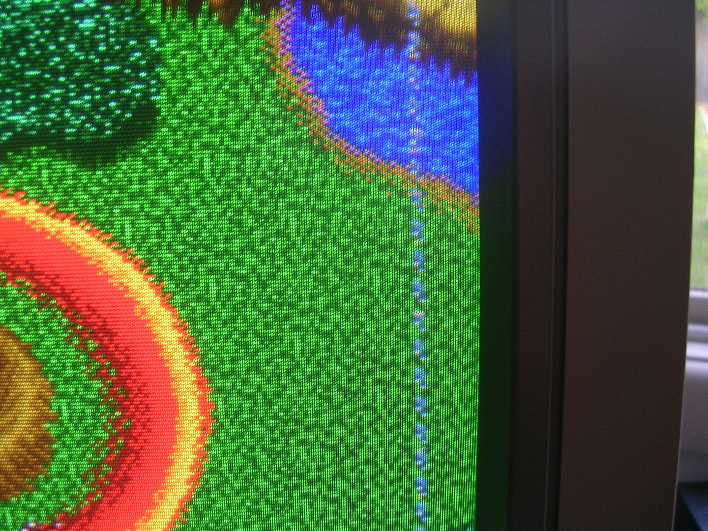
Problem solved, the MB3730 would now only get warm and not overheat. So I swapped it into my cabinet for a game and blasted through the first level and called the board fixed!
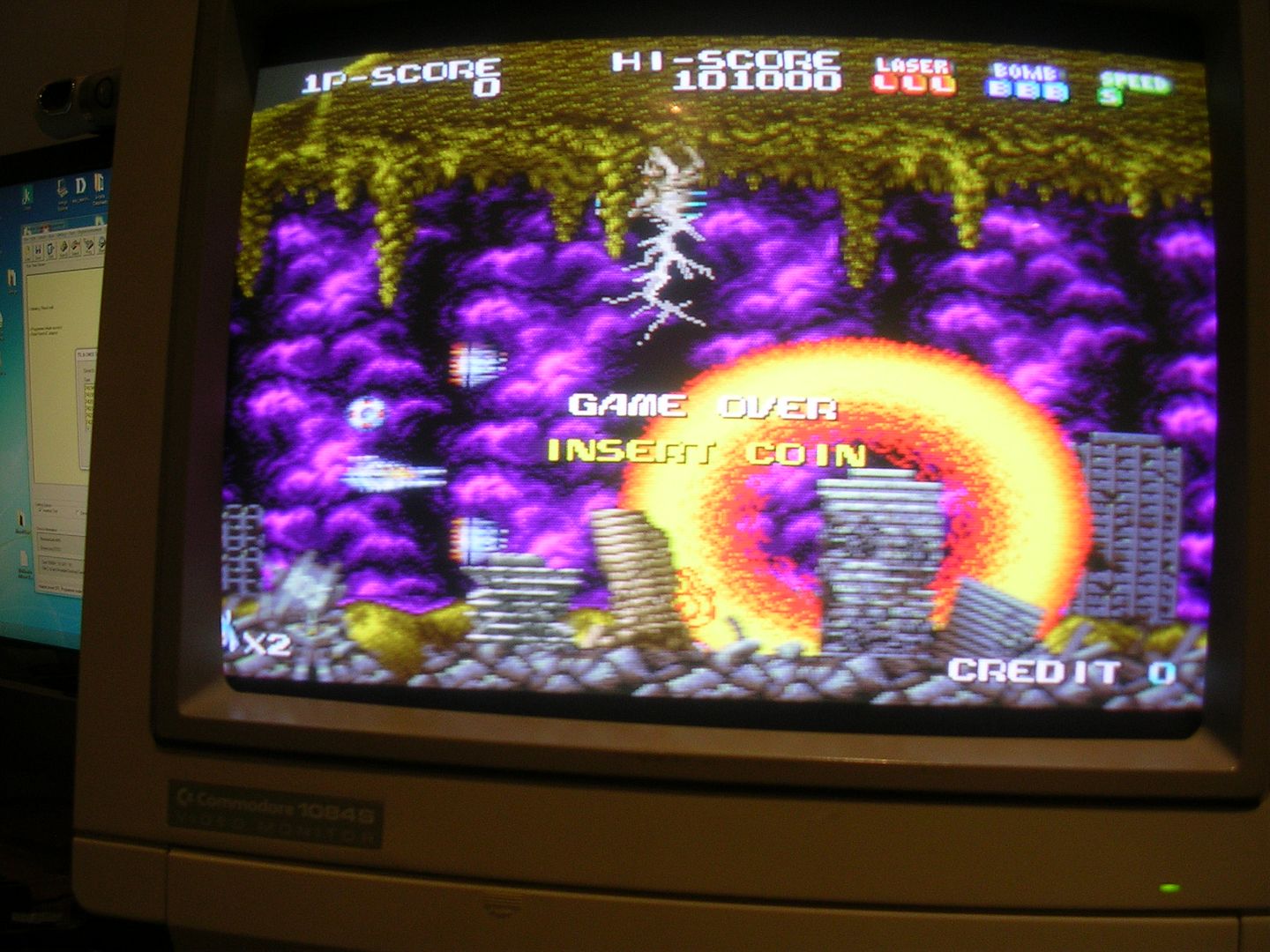
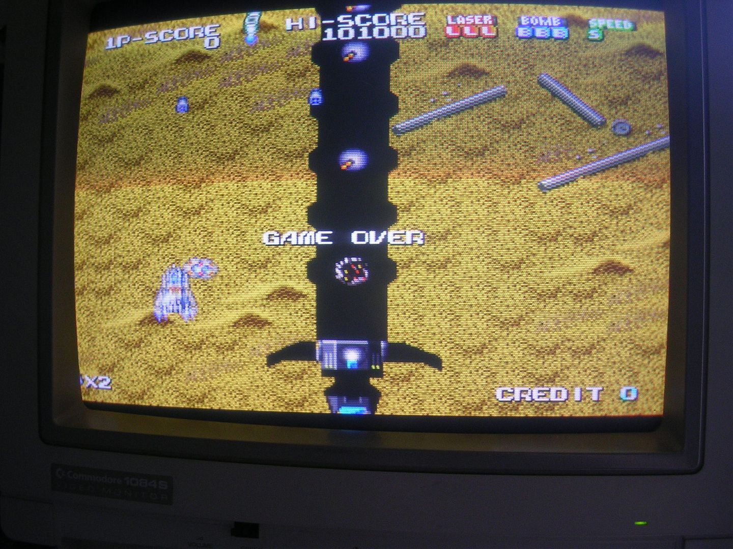
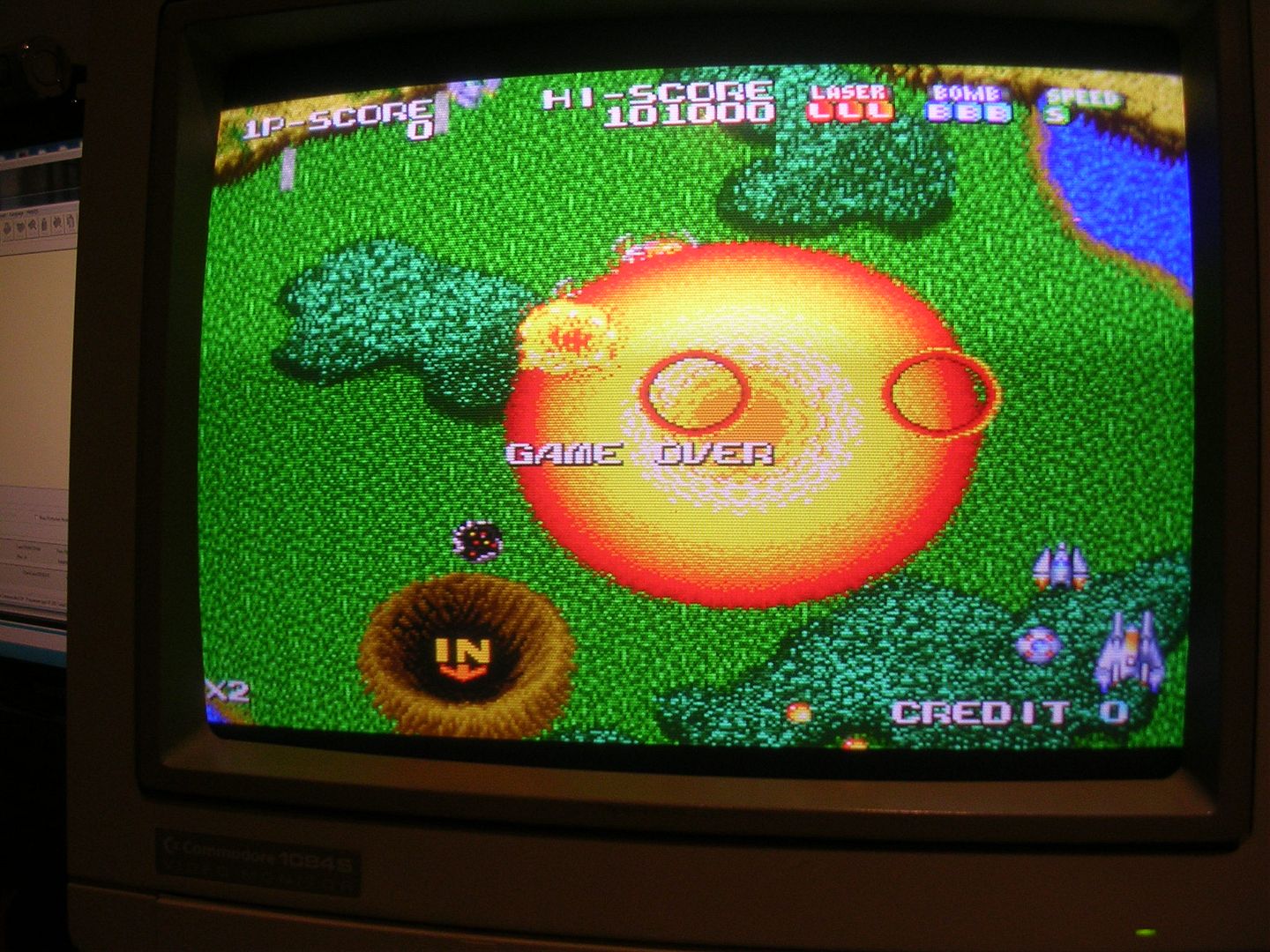
Or not, the following day I had planned to find the right stand-offs for it and bolt it together finally, except on power up for another game I was greeted with this.