MVS-U4-DK (Dino King Conversion)

Show off your wares.
User avatar
zipper
Posts: 122
Joined: March 20th, 2015, 11:47 am
Location: Southend on Sea
eBay: bazpatts
Initials: BAZ

MVS-U4-DK (Dino King Conversion)

Post by zipper »

This is my project for the summer. I'm getting a Dino King this week, and am converting it to a small form MVS cab.
EDIT... Finished:

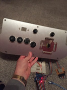
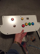
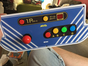
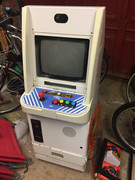
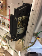
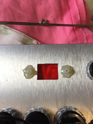
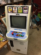
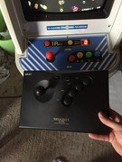
I've got the control panel (thanks Virtvic) cut, and overlay (thanks Muddymusic) applied.
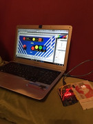
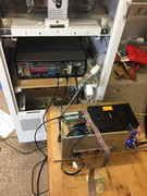
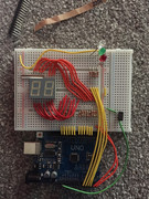
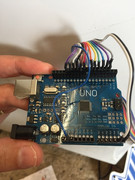
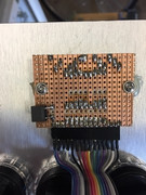
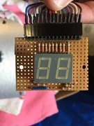
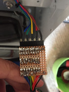
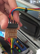
I've connected it up to a MAME (emulating a 4-slot), with MAME Hooker and Arduino powering the credits (a 2-digit, 7-segment led on some veroboard) :

I'm going to light up mini marquees too.. and have this working really well on a breadboard at the moment:


Still to do:
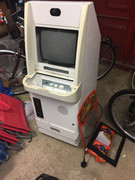
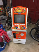
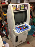
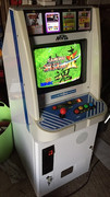
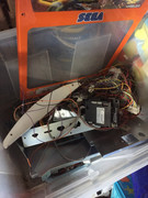
1/ Get the cab and strip out the DK bits + art.
2/ Add a small de-cased windows PC, probably core2duo, running groovymame.
3/ Add a memory card slot and headphone jack under the control panel.
4/ Finish drawing the rest of the art and get it printed and applied
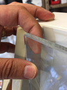
5/ Cut a clear acrylic bezel.
6/ Look at changing the coin mach to 100 yen.

Here's the arduino code if anyone wants to have a go:

Code: Select all

// Dual seven-segment LED Display
// Common Anode digit 1 pin 14
// Common Anode digit 2 pin 13

//   F G A B C1   C2 M H I  
//   | | | | |     | | | |   -> pins and segments they control
//   ---------    ---------
//   |   A   |    |   H   |
//  F|       |B  M|       |I
//   |---G---|    |---N---|
//  E|       |C  L|       |J
//   |   D   |    |   K   |
//   ---------    ---------
//   | | | |  |    | | | |   -> pins and segments they control
//   E D C D1 L    K N J D2           

// Segments that make each number when lit:
// 0 => -FEDCBA
// 1 => ----BC-
// 2 => G-ED-BA
// 3 => G--DCBA
// 4 => GF--CB-
// 5 => GF-DC-A
// 6 => GFEDC-A
// 7 => ----CBA
// 8 => GFEDCBA
// 9 => GF-DCBA

// Arduino digital pins used to light up
// corresponding segments on the LED display
#define A 2
#define B 6
#define C 5
#define D 4
#define E 3
#define F_SEG A5
#define G A4
#define H 13
#define I 11
#define J 10
#define K 8
#define L 7
#define M 12
#define N 9
#define W A0
#define X A1
#define Y A2
#define Z A3


// Pins in sequence
const int segs1[7] = { A, B, C, D, E, F_SEG, G };
const int segs2[7] = { H, I, J, K, L, M, N };
const int lamps[4] = { W, X, Y, Z };


// Segments that make each number
const byte numbers[10] = { 0b1000000, 0b1111001, 0b0100100, 0b0110000, 0b0011001, 0b0010010, 0b0000010, 0b1111000, 0b0000000, 0b0010000 };
const byte marquees[4] = { 0b1110, 0b1101, 0b1011, 0b0111 };


const char startOfNumberDelimiter = '<';
const char endOfUnitsDelimiter   = 'U';
const char endOfTensDelimiter   = 'T';
const char endOfMarqDelimiter   = 'M';

void setup ()
  { 
  for (int i = 0; i < 7; i++) {
    digitalWrite(segs1[i], 1);
    digitalWrite(segs2[i], 1);
  }
  for (int i = 0; i < 4; i++) {
  digitalWrite(lamps[i], 1);
  }
  Serial.begin (9600);
  pinMode(A, OUTPUT);
  pinMode(B, OUTPUT);
  pinMode(C, OUTPUT);
  pinMode(D, OUTPUT);
  pinMode(E, OUTPUT);
  pinMode(F_SEG, OUTPUT);
  pinMode(G, OUTPUT);
  pinMode(H, OUTPUT);
  pinMode(I, OUTPUT);
  pinMode(J, OUTPUT);
  pinMode(K, OUTPUT);
  pinMode(L, OUTPUT);
  pinMode(M, OUTPUT);
  pinMode(N, OUTPUT);
  pinMode(W, OUTPUT);
  pinMode(X, OUTPUT);
  pinMode(Y, OUTPUT);
  pinMode(Z, OUTPUT);
  }

void processNumber (const int n, const int location)
  {
    int digit;
    switch(n) {
      case 6: digit=1; break;
      case 91: digit=2; break;
      case 79: digit=3; break;
      case 102: digit=4; break;
      case 109: digit=5; break;
      case 125: digit=6; break;
      case 7: digit=7; break;
      case 127: digit=8; break;
      case 111: digit=9; break;
      default: digit=0; break;
    }
    if (location==2){
          for (int i = 0; i < 7; i++) {
          int bit = bitRead(numbers[digit], i);
          digitalWrite(segs2[i], bit);
          }
    } else if (location==1) {
        if (digit==0){
          for (int i = 0; i < 7; i++) {
          int bit = bitRead(numbers[digit], i);
          digitalWrite(segs1[i], 1);
          }
        } else {
          for (int i = 0; i < 7; i++) {
          int bit = bitRead(numbers[digit], i);
          digitalWrite(segs1[i], bit);
          }
        }
    } else {
          for (int i = 0; i < 4; i++) {
          int bit = bitRead(marquees[digit-1], i);
          digitalWrite(lamps[i], bit);
          }
    }
}  // end of processNumber
  
void processInput ()
  {
  static int receivedNumber = 0;
  byte c = Serial.read ();
  switch (c)
    {
    case endOfUnitsDelimiter:  
        processNumber (receivedNumber, 2); 
        break;
    case endOfTensDelimiter:
        processNumber (receivedNumber, 1); 
        break;
    case endOfMarqDelimiter:
        processNumber (receivedNumber, 3); 
        break;
    case startOfNumberDelimiter: 
      receivedNumber = 0; 
      break;
    case '0' ... '9': 
      receivedNumber *= 10;
      receivedNumber += c - '0';
      break;
    }
  }
  
void loop ()
  {
  while (Serial.available ())
    processInput ();
  }
Image gallery...
Image Image Image Image

Image Image Image Image

Image Image Image Image

Image Image Image Image

Image Image Image Image

Image Image Image Image

Image Image Image Image
Last edited by zipper on October 9th, 2018, 1:57 pm, edited 2 times in total.
User avatar
frsj8112
Posts: 95
Joined: April 11th, 2012, 6:06 pm
Location: Sweden
eBay: frsj8112

Re: MVS-U4-DK (Dino King Conversion)

Post by frsj8112 »

Wow great job mate :thumbupright:
User avatar
zak
Acetated
Posts: 1720
Joined: October 19th, 2014, 1:35 pm
Location: UK
eBay: NA

Re: MVS-U4-DK (Dino King Conversion)

Post by zak »

Awesome to the max! :)

Wouldn't you rather wire in a 4-slot board?
User avatar
zipper
Posts: 122
Joined: March 20th, 2015, 11:47 am
Location: Southend on Sea
eBay: bazpatts
Initials: BAZ

Re: MVS-U4-DK (Dino King Conversion)

Post by zipper »

zak wrote:Awesome to the max! :)

Wouldn't you rather wire in a 4-slot board?
Thanks guys.
I would prefer a 4-slot, yeah :lol: - but I really fancied messing around with an arduino, electronics and mame hooker to be honest.I don't think anyone has fed a credit LED / marquee lights from MAME before.
User avatar
zak
Acetated
Posts: 1720
Joined: October 19th, 2014, 1:35 pm
Location: UK
eBay: NA

Re: MVS-U4-DK (Dino King Conversion)

Post by zak »

zipper wrote:
zak wrote:Awesome to the max! :)

Wouldn't you rather wire in a 4-slot board?
Thanks guys.
I would prefer a 4-slot, yeah :lol: - but I really fancied messing around with an arduino, electronics and mame hooker to be honest.I don't think anyone has fed a credit LED / marquee lights from MAME before.
The panel looks amazing! I can't wait to see the rest of the cab!

how much space do you have in there? Would a full size 4 slot fit?
User avatar
Flinnster
Please Continue...
Posts: 332
Joined: September 19th, 2016, 12:06 am
Location: Surrey
eBay: flinnster
Initials: KID

Re: MVS-U4-DK (Dino King Conversion)

Post by Flinnster »

Right on! That CP looks f####g epic! :D
WTD: Rolling Thunder pcb, ANY Dino King / Love & Berry / MushiKing spare parts!!
User avatar
Hellfromabove
Please Continue...
Posts: 367
Joined: January 8th, 2009, 11:19 am
Location: SoCal

Re: MVS-U4-DK (Dino King Conversion)

Post by Hellfromabove »

zipper wrote: I don't think anyone has fed a credit LED / marquee lights from MAME before.
I was dabbling with a similar concept with the credits on a dual 2 Slot/ Pi setup. I'll send you a PM as I have questions.

Great job, it's looking fantastic!
User avatar
zipper
Posts: 122
Joined: March 20th, 2015, 11:47 am
Location: Southend on Sea
eBay: bazpatts
Initials: BAZ

Re: MVS-U4-DK (Dino King Conversion)

Post by zipper »

Thanks :D
The cabinet arrived today.... So stripped the Dino King art and popped the MVS panel on to take a look. Fits perfect :)
I've ordered a clear replacement bezel - should be here next week. The new art for the bezel, front and sides it coming together.
ImageImage
It's smaller than I imagined - very cute little cab.
User avatar
Flinnster
Please Continue...
Posts: 332
Joined: September 19th, 2016, 12:06 am
Location: Surrey
eBay: flinnster
Initials: KID

Re: MVS-U4-DK (Dino King Conversion)

Post by Flinnster »

Looking good! Is your original orange Sega bezel damaged in any way? If you don't need it I could do with a spare :)
WTD: Rolling Thunder pcb, ANY Dino King / Love & Berry / MushiKing spare parts!!
User avatar
Hellfromabove
Please Continue...
Posts: 367
Joined: January 8th, 2009, 11:19 am
Location: SoCal

Re: MVS-U4-DK (Dino King Conversion)

Post by Hellfromabove »

Lookin' solid sir!
User avatar
zipper
Posts: 122
Joined: March 20th, 2015, 11:47 am
Location: Southend on Sea
eBay: bazpatts
Initials: BAZ

Re: MVS-U4-DK (Dino King Conversion)

Post by zipper »

Had a bit of time today, so emptied the cab. Once the Dino King stuff is stripped out, there's quite a lot of space. No need to decase the pc, it sits very nicely on the top shelf. Monitor plugs straight in:
Imageuploading pictures
The 2nd shelf will have the ipac, arduino, service panel and amplifier. I'll move the power supply to the bottom of the cabinet.
I can't stand electronic coin mechs (I can never get them to work properly!), so swapped the S4 out for a good mechanical 100Yen one. I've not wired the switch yet and need to tidy it:
Imagefree pic
The speaker sounds great. I got a little stereo to mono adaptor, and a little 12v amp.
The picture straight out of the PC looks superb:
Imageadult image hosting
Looking forward to cleaning it up, getting the artwork completed and printed and finishing it off. It's a really nice cab to work with!
User avatar
zipper
Posts: 122
Joined: March 20th, 2015, 11:47 am
Location: Southend on Sea
eBay: bazpatts
Initials: BAZ

Re: MVS-U4-DK (Dino King Conversion)

Post by zipper »

Flinnster wrote:Looking good! Is your original orange Sega bezel damaged in any way? If you don't need it I could do with a spare :)
It's a bit scratched but not too bad. Sure - if all goes to plan with the replacement, I won't be needing it.
User avatar
FcoBenitez
Please Continue...
Posts: 361
Joined: August 18th, 2008, 3:31 am
Location: Chile
eBay: virtuacl
Initials: KBL

Re: MVS-U4-DK (Dino King Conversion)

Post by FcoBenitez »

OMG thanks for the Arduino code :o !!
2X Sega Aero City
User avatar
Flinnster
Please Continue...
Posts: 332
Joined: September 19th, 2016, 12:06 am
Location: Surrey
eBay: flinnster
Initials: KID

Re: MVS-U4-DK (Dino King Conversion)

Post by Flinnster »

A pretty epic build this one! :)
WTD: Rolling Thunder pcb, ANY Dino King / Love & Berry / MushiKing spare parts!!
User avatar
FrancoB
J+ member of the year finalist!
Posts: 4803
Joined: June 8th, 2009, 10:42 pm
Location: Oxfordshire
eBay: francosquashking
Initials: FRN

Re: MVS-U4-DK (Dino King Conversion)

Post by FrancoB »

Wowserz. Great work so far! :awe:

There is a surprising amount of space in these things once you strip everything out.

Looking forward to seeing this progress :) :thumbupright:
User avatar
Beaps
Please Continue...
Posts: 127
Joined: December 29th, 2008, 6:37 pm
Location: Essex - UK

Re: MVS-U4-DK (Dino King Conversion)

Post by Beaps »

Wow this looks awesome, would love to do a similar thing with the lights on my original U4 as having em all perminatly lit is a bit naff
User avatar
geotrig
Potato!
Posts: 7786
Joined: December 5th, 2008, 1:14 pm
Location: ._.
eBay: ._.

Re: MVS-U4-DK (Dino King Conversion)

Post by geotrig »

Excellent stuff , the cp is ace as well as the lights ,looking forward to seeing this progress
Image

<trk>:I remember catching a big fat one and my friend said "throw it back in, that one already tastes like wood"
User avatar
zipper
Posts: 122
Joined: March 20th, 2015, 11:47 am
Location: Southend on Sea
eBay: bazpatts
Initials: BAZ

Re: MVS-U4-DK (Dino King Conversion)

Post by zipper »

There's been some interest, so I'll detail the process of building the credit display in this post. Just incase it's not clear.. what I built below doesn't count credits, it only displays them... it's the emulated MVS that counts the credits and sends the number to the display.... so this will only work with MVS.

For those interested, grab yourself an Arduino Uno. It can be one of the knock-offs that cost about a fiver (like mine!)... if you get one of those then you'll probably have to install an additional driver (CH341SER) : https://www.diy-india.com/make/arduino- ... ected.html. I recommend doing the 'blink' tutorial to prove you can write to the Arduino and that it's working : https://www.arduino.cc/en/tutorial/blink. It's like a standard 'hello world'. You don't need the resistor or LED, as pin 13 has a little LED on the board itself - you just need the arduino.

Once you are happy you can use the Arduino, upload the code from the first post using the Arduino dev environment (https://www.arduino.cc/). It's heavily based on this tutorial - so credit to them: http://www.tinkerhobby.com/arduino-2-di ... y-counter/
You then want to install Mamehooker: http://dragonking.arcadecontrols.com/st ... mamehooker
This is where the magic is. Full credit to the guy behind that app. The download link is on the right (MameHooker 5.1).
You want to change both MAME and Mamehooker executable files to run with admin privs (right click, compatibility, tick run as admin).... I found it was needed to use windows outputs (it's how mamehooker communicates). So in your mame.ini file set:

Code: Select all

#
# OSD OUTPUT OPTIONS
#
output                    windows
To get mamehooker editor working properly I had to download and register richtx32.ocx : http://www.k6jm.com/hs-setupocx.htm
Set mamehooker up by telling it where your mame directory + executable are.
Then you want to create 'neogeo.cpp.ini' in the mamehooker/ini/MAME folder.... Mine looks like this:

Code: Select all

[General]
MameStart=cmo 3 baud=9600_parity=N_data=8_stop=1
MameStop=cmc 3
StateChange=
OnRotate=
OnPause=
[Output]
blank=
digit0=cmw 3 <,cmw 3 %s%,cmw 3 M
digit1=cmw 3 <,cmw 3 %s%,cmw 3 T
digit2=cmw 3 <,cmw 3 %s%,cmw 3 U
digit3=
digit4=
[KeyStates]
RefreshTime=
This is a little complex, but take time to understand it and you'll be good. It took me a couple of nights to wrap my head around it.
CMO = Com Port Open
CMC = Com Port Close
CMW = Com Port Write
< = Start of data flag
%s% = data
M, T and U = End of data flag (for Marquee, Tens and Units counter respectively).
I am sending data for digit0(the Marquee), digit1(the Tens leds) and digit2(the Units leds) over com port 3. This is crucial to understand, because you probably wont be sending over com port 3, it can be any number depending on which USB port you use - you will know what number to use when you program your arduino.
Make sure the Mamehooker is running, then start up neo geo in MAME.... This is how you get it emulating a 4-slot:

Code: Select all

mame.exe neogeo -cart1 samsho2 -cart2 turfmast -cart3 mslugx -cart4 pbobbl2n
Because it's emulating the MVS 4-slot, it's also emulating the MVS-LED! Adding credits should see the little 'data received' LED (rx/tx) on the UNO flicker... That's MAME/MameHooker forwading the credit information over the COM port. If you see that, then you are good. You need to plug your LED counter into the UNO at this point...
All you need for this is a 2-digit, 7-segment led (with common anode)... e.g. from Maplin: http://www.maplin.co.uk/p/14mm-red-2x7- ... play-by66w
Get some veroboard and a soldering iron - standard stuff for knocking up prototypes. You'll need 14x 220 ohm resistors (one for each segment - each segment is just an LED), and a little link wire. I've put a 1 amp fuse on the +5v rail too... but not really needed. FYI - You can put a circuit break in the copperrails by twisting a 2-3mm drillbit in the holes with your fingers (the circles in the picture below):
ImageImage
The arduino code has the pinout of the display chip in the comments at the top. You can fold the dp (decimal point) pins down as they are not needed. You need to connect both the anodes to the +5v rail. Get yourself some ribbon cable (at least 15wires).. 'Search Multi Coloured Ribbon Cable AWG 28' on ebay and you'll get loads of options - don't spend more than a fiver.
You need some connectors.... https://www.coolcomponents.co.uk/ is brill.
This for your veroboard: https://www.coolcomponents.co.uk/en/hea ... -male.html
This for the veroboard end of the cable: https://www.coolcomponents.co.uk/en/fem ... 0-pin.html (you can cut these down with a mini hacksaw).
This for the arduino end of the cable: https://www.coolcomponents.co.uk/en/hea ... -male.html
You need to strip and solder the cable to the headers - bit fiddly - i recommend some heatshrink over each connection to keep it all nice and tidy.
Here's the cable plugged into the arduino:
Image
Every pin is labelled, and is assigned to an LED in the arduino code (1st post). The blue wire on its own is the +5v.
(more to come, but there's loads of info here for those that are interested!)
User avatar
Beaps
Please Continue...
Posts: 127
Joined: December 29th, 2008, 6:37 pm
Location: Essex - UK

Re: MVS-U4-DK (Dino King Conversion)

Post by Beaps »

Parts ordered ;-)
User avatar
zipper
Posts: 122
Joined: March 20th, 2015, 11:47 am
Location: Southend on Sea
eBay: bazpatts
Initials: BAZ

Re: MVS-U4-DK (Dino King Conversion)

Post by zipper »

I think i've settled on the bezel layout and tested it out on some paper. I'll get this one printed out on window sticker:
Image
Have got a nice bezel cut.... Need to drill the holes (it had better not crack):
Image
Will get the art on window sticker vinyl.