Donecrunchywasp wrote:Please add me to the cc list
Sega Dinosaur King cab - Conversion to JAMMA - Updated 31/3/16
-
Paulie

- Opens wallet, moths fly out
- Posts: 2599
- Joined: September 28th, 2011, 5:43 pm
- Location: East Ardsley, West Yorks
- eBay: retro-paulie
- Initials: PSG
Re: Sega Dinosaur King conversion to JAMMA
-
crunchywasp

- stompin' an' jumpin'
- Posts: 8101
- Joined: February 10th, 2012, 2:51 pm
- Location: Northern Ireland
- eBay: crunchywasp
- Initials: MAK

-
trev1976

- Posts: 881
- Joined: March 30th, 2009, 7:17 pm
- Location: Southampton
Re: Sega Dinosaur King conversion to JAMMA
Looks good , what did you use to cut the MDF ? I could do with making some mounting boards too
Thanks
Thanks
Check out my "1cc" YouTube Channel
YouTube
YouTube
-
emphatic

- Breastfeeds when required
- Posts: 5907
- Joined: April 7th, 2009, 4:14 pm
- Location: Alingsås, Sweden
- eBay: jorgen_sjolander
- Initials: JOR
-
Paulie
- Opens wallet, moths fly out
- Posts: 2599
- Joined: September 28th, 2011, 5:43 pm
- Location: East Ardsley, West Yorks
- eBay: retro-paulie
- Initials: PSG
Re: Sega Dinosaur King conversion to JAMMA
Thanks chaps 
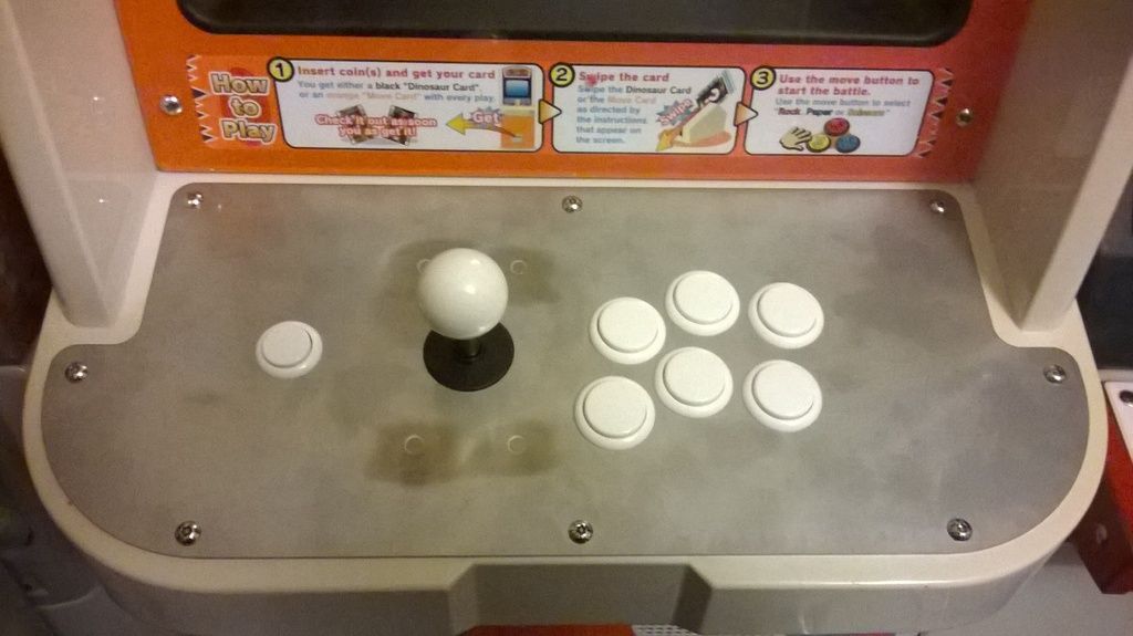
Although I had made my own control panels (not quite finished yet, but I will do as they are rather nice, see an older post) I also picked up a pair of 1L6B and a pair of blank panels from FrancoB. They were really cheap and are of excellent quality. TBH I should have picked up a pair of each layout that Fran was having fabricated as they really are bang on. I have a few spare sticks but decided to install Seimitsu LS32’s. I also have loads and loads of unused Sanwa and Seimitsu buttons and ball tops (mostly silly colours) but last year Jase sold me a set of black and a set of white Sanwa’s so that’s what I’ve populated the control panels with, also I've not yet decided on what art I'll use, so this colour scheme may have to change.
Cheers F-Man
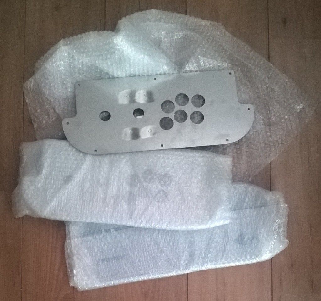
Just need to sort an overlay out now
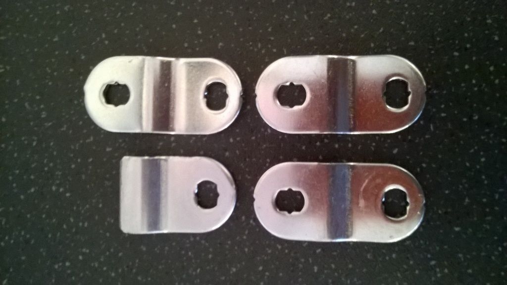
Locks: I’ve now got them sorted, not OEM but I’m not fussed as it’s hardly an original cab. Made a bit of a FUBAR, I ordered some that had stepped tangs, I took a punt as I guessed that they would probably fit but they didn’t. devilsoundwave was a complete gent and insisted that I return them to back to him AKA arcadejapan for a full refund so a free plug for him and his store http://www.arcadejapan.co.uk/ what a good egg! I ended up buying a lot of 5x 19mm keyed alike locks for a little under £20 on ebay. The tangs needed to be cut to length as the cab requires a stubby tang but other than that they're fine. It only takes 30 seconds with a jigsaw to cut each tang to size, then a few minutes with a file to take off any burs and shape the corners.
One tang cut 3 more to go
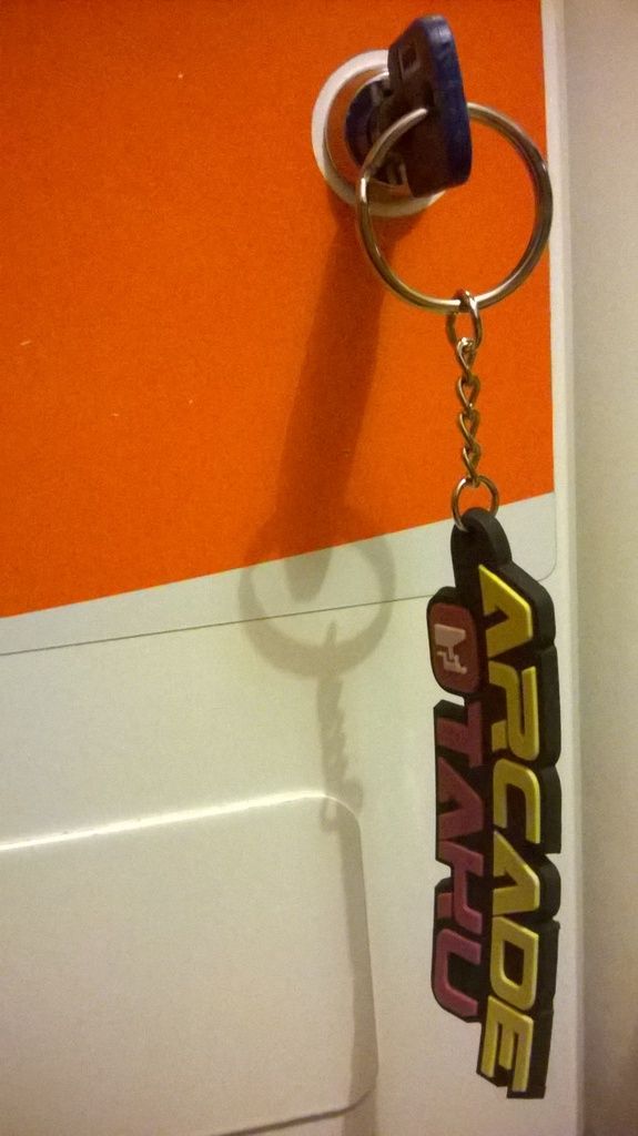
Fitted, yeah its only a lock but I'm using one of devilsoundwave's snazzy AO key chains so worthy of a photo
I used a jigsaw but it depends on what tools you have, and what you are cutting. As I said I would have finished this off with a router but I'm going to make them again when I have some spare MDF that matches the originals depth. If you are just wanting 90 degree cuts then you could use a table or circular saw, although most merchants offer a free or very cheap cutting service and I often take advantage of that. For something shaped then a jigsaw, freehand or used with a guide. Although as long as you are careful a hand saw will do the job, it may not be perfect but a sanding block should neaten things uptrev1976 wrote:what did you use to cut the MDF
Although I had made my own control panels (not quite finished yet, but I will do as they are rather nice, see an older post) I also picked up a pair of 1L6B and a pair of blank panels from FrancoB. They were really cheap and are of excellent quality. TBH I should have picked up a pair of each layout that Fran was having fabricated as they really are bang on. I have a few spare sticks but decided to install Seimitsu LS32’s. I also have loads and loads of unused Sanwa and Seimitsu buttons and ball tops (mostly silly colours) but last year Jase sold me a set of black and a set of white Sanwa’s so that’s what I’ve populated the control panels with, also I've not yet decided on what art I'll use, so this colour scheme may have to change.
Cheers F-Man

Just need to sort an overlay out now

Locks: I’ve now got them sorted, not OEM but I’m not fussed as it’s hardly an original cab. Made a bit of a FUBAR, I ordered some that had stepped tangs, I took a punt as I guessed
One tang cut 3 more to go

Fitted, yeah its only a lock but I'm using one of devilsoundwave's snazzy AO key chains so worthy of a photo

Last edited by Paulie on November 26th, 2016, 7:57 pm, edited 1 time in total.
-
Paulie
- Opens wallet, moths fly out
- Posts: 2599
- Joined: September 28th, 2011, 5:43 pm
- Location: East Ardsley, West Yorks
- eBay: retro-paulie
- Initials: PSG
Re: Sega Dinosaur King conversion to JAMMA
Before Christmas I said that I would share how I made the looms and how I wired these cabs, quite a few people keep asking so here we go
Obviously there’s more than one way to skin a cat and I'm no expert, as I say I'm just sharing how I did it.
I disconnected both the Live 240v feed and the neutral line from the noise filter and separated the JST VL8P / JST VL8R connectors (just press the tab) and removed this loom from the cabinet.
I cut both the live and neutral lines in half. I then stripped the correct length of protective sheath off of the four ends of wire. Both live wires were inserted into a Wago 222-413, 3-way connector and both neutral wires were inserted into a second Wago 222-413, 3-way connector.
I stripped the protective sheath and preprepared both ends of a length of mains wire (the Live and neutral lines need to be approx 400mm but the earth needs to be a little longer, approx 500mm).
On the end of the cable (with the longer length of earth) the live wire was inserted into the ‘live’ Wago connector and the neutral wire was inserted into the ‘neutral’ wago connector. Each end of the earth as well as the other end of the live and neutral lines were crimped with 4mm uninsulated ring terminals and heatshrink. Live, neutral and earth were connected to the appropriate screw terminals on the switching PSU. The other end of the earth (the long end) was screwed to the main earth terminal plate, the Live and neutral quick disconnects were reconnected back to the noise filter and the JST VL8P / JST VL8R connectors were reconnected.
The loom
This is pretty standard stuff really.
I picked up a couple high quality preloved looms from Mo which I adapted, I did make my own loom from scratch but used that one on another project. If you want to make one from scratch use 16/0.2 (~20AWG) for signal and 24/0.2 (~18AWG) for power.
I put the wires into 6 bundles (a Bob Roberts tip) hence the colour coding.
Black/Grey - Main Power - A,B,C,D,E,F,1,2,3,4,5
Yellow - Coin door - R,e,6,8,15,16
Orange - Audio - L,10,
Blue - Video - N,P,12,13,14
Red - Player 1 - 17,18,19,20,21,22,23,24,25,27,28
Green - Player 2 - U,V,W,X,Y,Z,a,b,c,f
Front view
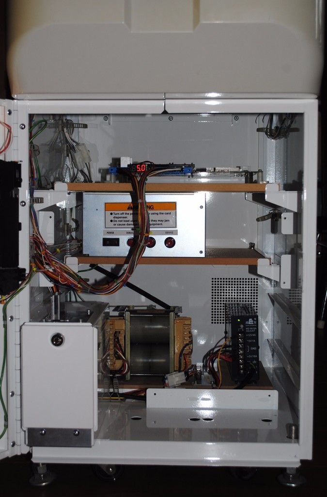
Back view

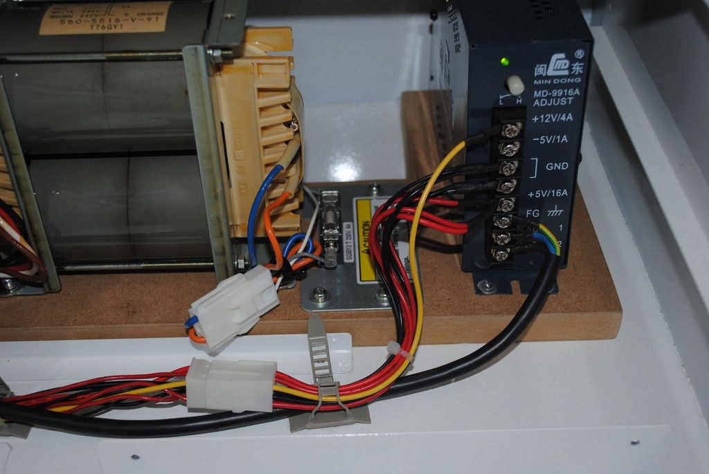
Main Power (BLACK/GREY bundle - A,B,C,D,E,F,1,2,3,4,5)
All wires wires A (GND), B (GND), C (+5vDC), D (+5vDC), E ( -5vDC), F (+12vDC), 1 (GND), 2 (GND), 3 (+5vDC), 4 (+5vDC) and 5 ( -5vDC) terminate with 4mm uninsulated ring terminals/ heat shrink and are connected to the appropriate screw terminals on the switching PSU. To enable quick removal of the switching PSU I added a 12 pin AMP UP break out connector.
NOTE: One of my cabs has a Min Dong PSU which doesn't support -5vDC so in that cab E ( -5vDC) and 5 ( -5vDC) are terminated in a 2 pin AMP UP connector.
Main Power
Coin door (YELLOW bundle - R,e,6x2,8,15,16)
Service switch - R (Service switch) and e (GND), both terminate in 2.8mm uninsulated terminals / SR-110 sleeves and are connected to the service switch. I daisy chained a second length of wire to e (GND) and terminated it again in a 2.8mm uninsulated terminal / SR-110 sleeve to provide GND for the test switch. I then daisy chained a third length of wire to e (GND) which terminated in a .3.96mm/0.156” pitch crimp terminal which is connected to pin 3 on the Molex KK credit board connector, again to provide GND.
Test switch - 15 (test switch) terminates in a 2.8mm uninsulated terminal / SR-110 sleeve. GND is addressed as above.
Coin mech credit board - 6 (12vDC) to pin 1 (12vDC) and 16 (coin switch 1) to pin 4 (0P1) on the Molex KK connector, GND was daisy chained from e (GND) on the service switch as above.
Coin mech light - Pin 5 (12vDC) and pin 10 (0v GND) from the Molex KK connector on the credit board both terminating 2.8mm uninsulated terminals / SR-110 sleeves and connected to the coin mech light bulb holder. A massive thanks to Guy for helping me out with these
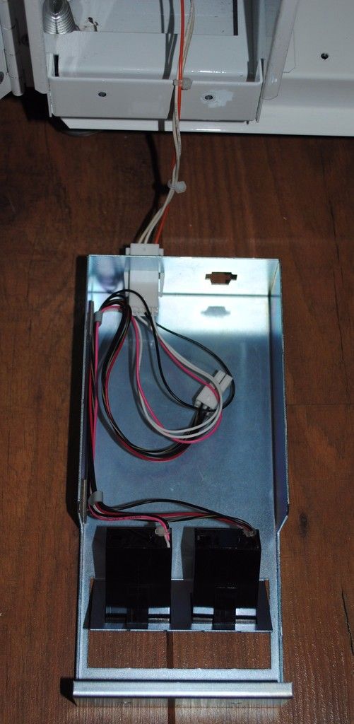
Coin counter - 6, 8 and from pin 10 on the Molex KK credit board connector all terminated in a JST YLR-06V connector. 6 (+12vDC) to pin 1, 8 (coin counter#1) to pin 2 and from pin 10 (0V GND) on the Molex KK credit board connector to pin 3.
Note there are two coin counters in this cab but you only need one of them, the other counter uses a JST YLR-04V connector so take ya pick.
Service & Test
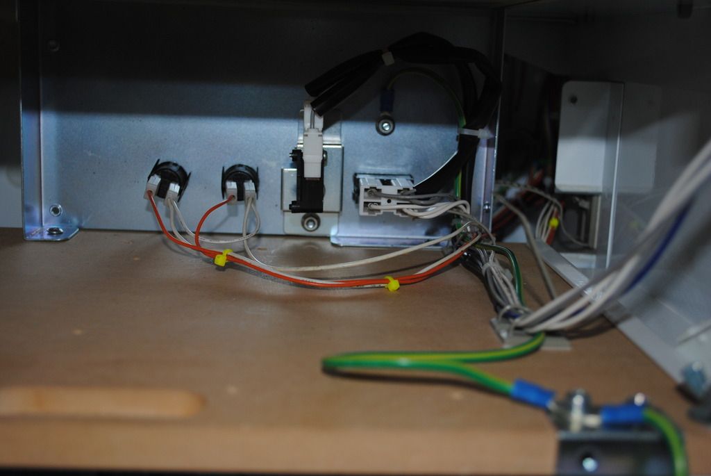
Front Door audio(ORANGE bundle - L,10) and coin mech
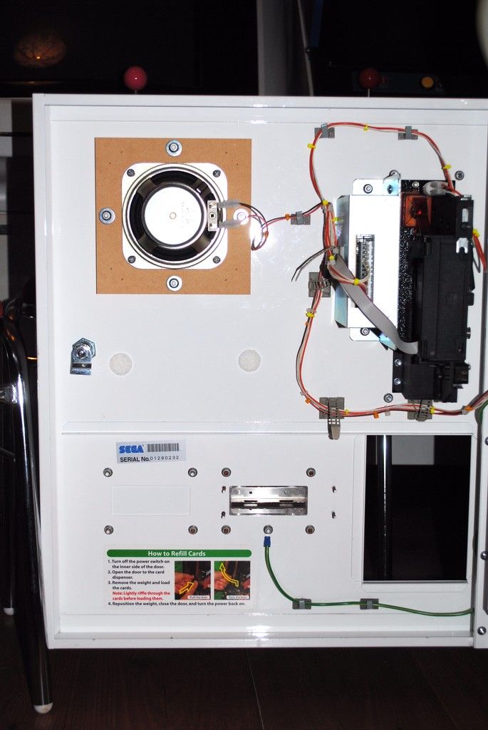
Coin counter
Video (BLUE bundle - N,P,12,13,14)
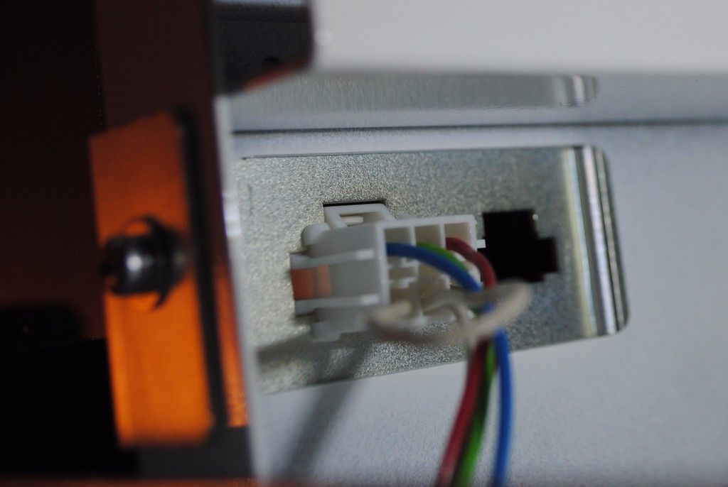
All cables terminate in a JST YLR-06V connector. 12 (video red) to pin 1, N (video green) to pin 2, 13 (video blue) to pin 3, 14 (video ground) to pin 4, P (video sync) to pin 5, I ran a jumper from pin 5 (video sync) to pin 6 to make composite video. This then connects to the JST YLP-06V which is the cabinets factory fitted monitor connection.
Video
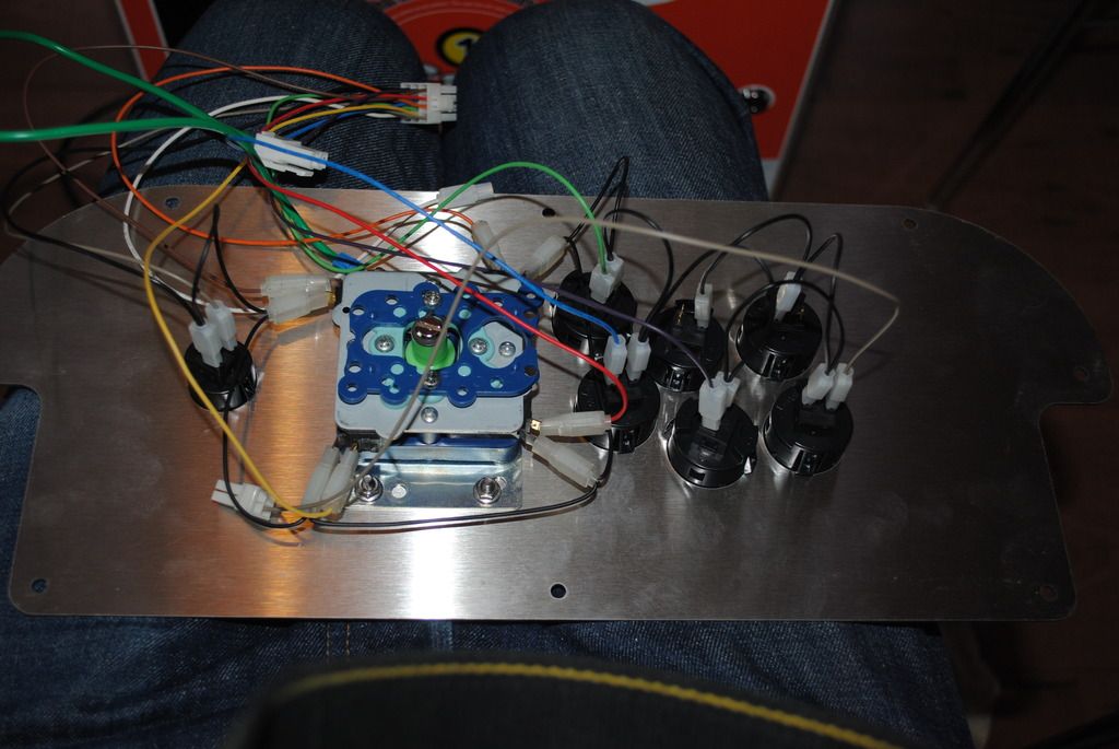
Player 1 (RED bundle - 17,18,19,20,21,22,23,24,25,27,28)
Joystick - 18 (up), 19 (down), 20 (left), 21 (right) and 28 (GND) all terminate in 4.8mm uninsulated terminal / SR-187 sleeves. 28 (GND) has a further three lengths of wire daisy chained terminating in 4.8mm uninsulated terminals / SR-187 sleeves. These are then all connected to a Seimitsu LS-32 joystick.
Pushbuttons - 17 (start), 22 (1), 23 (2), 24 (3), 25 (4) and 27 (GND) all terminate in 2.8mm uninsulated terminals / SR-110 sleeves. 27 has a further 6 lengths of wire daisy chained and terminating in 2.8mm uninsulated terminals / SR-110 sleeves. These are then all connected to the six Sanwa OBSF-30 and one Sanwa OBSF-24 push buttons.
To enable quick removal of the control panel I added a 12 pin AMP UP break out connector, 25 (button 4) has its own AMP UP break out connector. Post Naomi Sega cabs use JST VL and YL connectors but I used AMP UP as that’s what I had in my spares box.
Player 2 (GREEN bundle U,V,W,X,Y,Z,a,b,c,f)
Currently unused. U (start), V (up), W (down), X (left),Y (right), Z (1), a (2), b (3), c (4), f (GND) all terminating in a 12 pin AMP UP break out connector.
Boom!
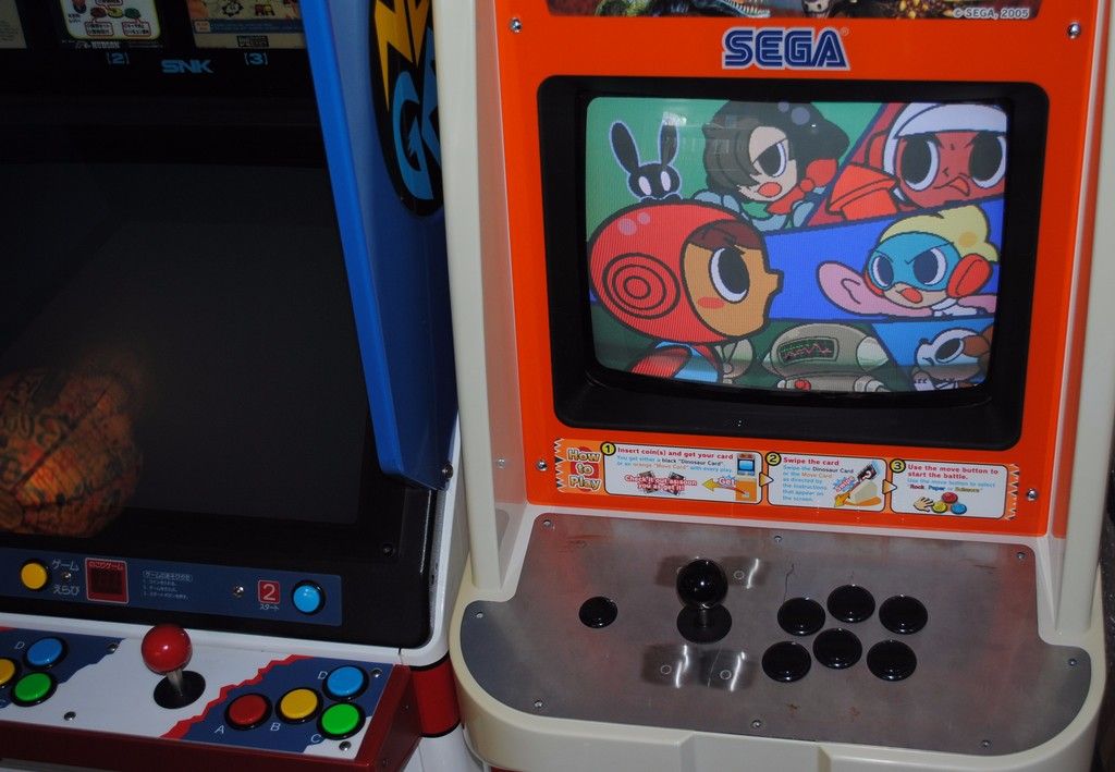
One of the cabs is currently being used as my dedicated PGM cab and the other is used for whatever. I say used in the loosest sense of the word as I don't seem to have time to fart these days. There’s still quite a few other jobs to do, but hey who’s rushing...
Obviously there’s more than one way to skin a cat and I'm no expert, as I say I'm just sharing how I did it.
I disconnected both the Live 240v feed and the neutral line from the noise filter and separated the JST VL8P / JST VL8R connectors (just press the tab) and removed this loom from the cabinet.
I cut both the live and neutral lines in half. I then stripped the correct length of protective sheath off of the four ends of wire. Both live wires were inserted into a Wago 222-413, 3-way connector and both neutral wires were inserted into a second Wago 222-413, 3-way connector.
I stripped the protective sheath and preprepared both ends of a length of mains wire (the Live and neutral lines need to be approx 400mm but the earth needs to be a little longer, approx 500mm).
On the end of the cable (with the longer length of earth) the live wire was inserted into the ‘live’ Wago connector and the neutral wire was inserted into the ‘neutral’ wago connector. Each end of the earth as well as the other end of the live and neutral lines were crimped with 4mm uninsulated ring terminals and heatshrink. Live, neutral and earth were connected to the appropriate screw terminals on the switching PSU. The other end of the earth (the long end) was screwed to the main earth terminal plate, the Live and neutral quick disconnects were reconnected back to the noise filter and the JST VL8P / JST VL8R connectors were reconnected.
The loom
This is pretty standard stuff really.
I picked up a couple high quality preloved looms from Mo which I adapted, I did make my own loom from scratch but used that one on another project. If you want to make one from scratch use 16/0.2 (~20AWG) for signal and 24/0.2 (~18AWG) for power.
I put the wires into 6 bundles (a Bob Roberts tip) hence the colour coding.
Black/Grey - Main Power - A,B,C,D,E,F,1,2,3,4,5
Yellow - Coin door - R,e,6,8,15,16
Orange - Audio - L,10,
Blue - Video - N,P,12,13,14
Red - Player 1 - 17,18,19,20,21,22,23,24,25,27,28
Green - Player 2 - U,V,W,X,Y,Z,a,b,c,f
Front view

Back view

Main Power (BLACK/GREY bundle - A,B,C,D,E,F,1,2,3,4,5)
All wires wires A (GND), B (GND), C (+5vDC), D (+5vDC), E ( -5vDC), F (+12vDC), 1 (GND), 2 (GND), 3 (+5vDC), 4 (+5vDC) and 5 ( -5vDC) terminate with 4mm uninsulated ring terminals/ heat shrink and are connected to the appropriate screw terminals on the switching PSU. To enable quick removal of the switching PSU I added a 12 pin AMP UP break out connector.
NOTE: One of my cabs has a Min Dong PSU which doesn't support -5vDC so in that cab E ( -5vDC) and 5 ( -5vDC) are terminated in a 2 pin AMP UP connector.
Main Power

Coin door (YELLOW bundle - R,e,6x2,8,15,16)
Service switch - R (Service switch) and e (GND), both terminate in 2.8mm uninsulated terminals / SR-110 sleeves and are connected to the service switch. I daisy chained a second length of wire to e (GND) and terminated it again in a 2.8mm uninsulated terminal / SR-110 sleeve to provide GND for the test switch. I then daisy chained a third length of wire to e (GND) which terminated in a .3.96mm/0.156” pitch crimp terminal which is connected to pin 3 on the Molex KK credit board connector, again to provide GND.
Test switch - 15 (test switch) terminates in a 2.8mm uninsulated terminal / SR-110 sleeve. GND is addressed as above.
Coin mech credit board - 6 (12vDC) to pin 1 (12vDC) and 16 (coin switch 1) to pin 4 (0P1) on the Molex KK connector, GND was daisy chained from e (GND) on the service switch as above.
Coin mech light - Pin 5 (12vDC) and pin 10 (0v GND) from the Molex KK connector on the credit board both terminating 2.8mm uninsulated terminals / SR-110 sleeves and connected to the coin mech light bulb holder. A massive thanks to Guy for helping me out with these
Coin counter - 6, 8 and from pin 10 on the Molex KK credit board connector all terminated in a JST YLR-06V connector. 6 (+12vDC) to pin 1, 8 (coin counter#1) to pin 2 and from pin 10 (0V GND) on the Molex KK credit board connector to pin 3.
Note there are two coin counters in this cab but you only need one of them, the other counter uses a JST YLR-04V connector so take ya pick.
Service & Test

Front Door audio(ORANGE bundle - L,10) and coin mech

Coin counter

Video (BLUE bundle - N,P,12,13,14)
All cables terminate in a JST YLR-06V connector. 12 (video red) to pin 1, N (video green) to pin 2, 13 (video blue) to pin 3, 14 (video ground) to pin 4, P (video sync) to pin 5, I ran a jumper from pin 5 (video sync) to pin 6 to make composite video. This then connects to the JST YLP-06V which is the cabinets factory fitted monitor connection.
Video

Player 1 (RED bundle - 17,18,19,20,21,22,23,24,25,27,28)
Joystick - 18 (up), 19 (down), 20 (left), 21 (right) and 28 (GND) all terminate in 4.8mm uninsulated terminal / SR-187 sleeves. 28 (GND) has a further three lengths of wire daisy chained terminating in 4.8mm uninsulated terminals / SR-187 sleeves. These are then all connected to a Seimitsu LS-32 joystick.
Pushbuttons - 17 (start), 22 (1), 23 (2), 24 (3), 25 (4) and 27 (GND) all terminate in 2.8mm uninsulated terminals / SR-110 sleeves. 27 has a further 6 lengths of wire daisy chained and terminating in 2.8mm uninsulated terminals / SR-110 sleeves. These are then all connected to the six Sanwa OBSF-30 and one Sanwa OBSF-24 push buttons.
To enable quick removal of the control panel I added a 12 pin AMP UP break out connector, 25 (button 4) has its own AMP UP break out connector. Post Naomi Sega cabs use JST VL and YL connectors but I used AMP UP as that’s what I had in my spares box.
Player 2 (GREEN bundle U,V,W,X,Y,Z,a,b,c,f)
Currently unused. U (start), V (up), W (down), X (left),Y (right), Z (1), a (2), b (3), c (4), f (GND) all terminating in a 12 pin AMP UP break out connector.

Boom!

One of the cabs is currently being used as my dedicated PGM cab and the other is used for whatever. I say used in the loosest sense of the word as I don't seem to have time to fart these days. There’s still quite a few other jobs to do, but hey who’s rushing...
Last edited by Paulie on November 26th, 2016, 8:13 pm, edited 2 times in total.
-
aeroflott

- Posts: 22
- Joined: November 24th, 2010, 11:28 am
- Location:
Re: Sega Dinosaur King conversion to JAMMA
Great post that. Thanks for sharing - useful info sir.
-
Paulie
- Opens wallet, moths fly out
- Posts: 2599
- Joined: September 28th, 2011, 5:43 pm
- Location: East Ardsley, West Yorks
- eBay: retro-paulie
- Initials: PSG
Re: Sega Dinosaur King cab - Conversion to JAMMA - Updated 31/3/16
No worries mate, glad you thought the info could be useful
I've added a photo of the coin counter as I'd missed that piccy when I originally posted.
I've added a photo of the coin counter as I'd missed that piccy when I originally posted.
-
Pirlo21Tifosi
- Please Continue...
- Posts: 6
- Joined: August 12th, 2016, 7:52 pm
- Location: France
Re: Sega Dinosaur King cab - Conversion to JAMMA - Updated 31/3/16
superb achievement!
I have the opportunity to purchase a Sega Dinosaur King Cab, I'd like to redo it completely to make a Duck Hunt spécial cab.
I have the opportunity to purchase a Sega Dinosaur King Cab, I'd like to redo it completely to make a Duck Hunt spécial cab.
-
NGAES

- Please Continue...
- Posts: 144
- Joined: August 28th, 2008, 5:40 pm
- Location: Stockholm, Sweden
-
FcoBenitez

- Please Continue...
- Posts: 361
- Joined: August 18th, 2008, 3:31 am
- Location: Chile
- eBay: virtuacl
- Initials: KBL
Re: Sega Dinosaur King cab - Conversion to JAMMA - Updated 31/3/16
Photobucket sux
2X Sega Aero City
-
Paulie
- Opens wallet, moths fly out
- Posts: 2599
- Joined: September 28th, 2011, 5:43 pm
- Location: East Ardsley, West Yorks
- eBay: retro-paulie
- Initials: PSG
Re: Sega Dinosaur King cab - Conversion to JAMMA - Updated 31/3/16
Thanks for letting me know I'll go though the photos over the weekend and get them back up
-
Paulie
- Opens wallet, moths fly out
- Posts: 2599
- Joined: September 28th, 2011, 5:43 pm
- Location: East Ardsley, West Yorks
- eBay: retro-paulie
- Initials: PSG
Re: Sega Dinosaur King cab - Conversion to JAMMA - Updated 31/3/16
I've done about half of them this evening and I'll do the rest soon, it's a far more tedious task than I first thoughtNGAES wrote:Pictures gone.
-
mission65

- Please Continue...
- Posts: 93
- Joined: May 17th, 2013, 4:04 pm
- Location: Kent
Re: Sega Dinosaur King cab - Conversion to JAMMA - Updated 31/3/16
If you get a chance to up the remaining pics, I would be most grateful
-
Paulie
- Opens wallet, moths fly out
- Posts: 2599
- Joined: September 28th, 2011, 5:43 pm
- Location: East Ardsley, West Yorks
- eBay: retro-paulie
- Initials: PSG
Re: Sega Dinosaur King cab - Conversion to JAMMA - Updated 31/3/16
no worries mate, I'll try and do it this weekend
-
Paulie
- Opens wallet, moths fly out
- Posts: 2599
- Joined: September 28th, 2011, 5:43 pm
- Location: East Ardsley, West Yorks
- eBay: retro-paulie
- Initials: PSG
Re: Sega Dinosaur King cab - Conversion to JAMMA - Updated 31/3/16
Finally got around to fixing the rest of the photos.
I posted this somewhere else but may as well stick it here too.
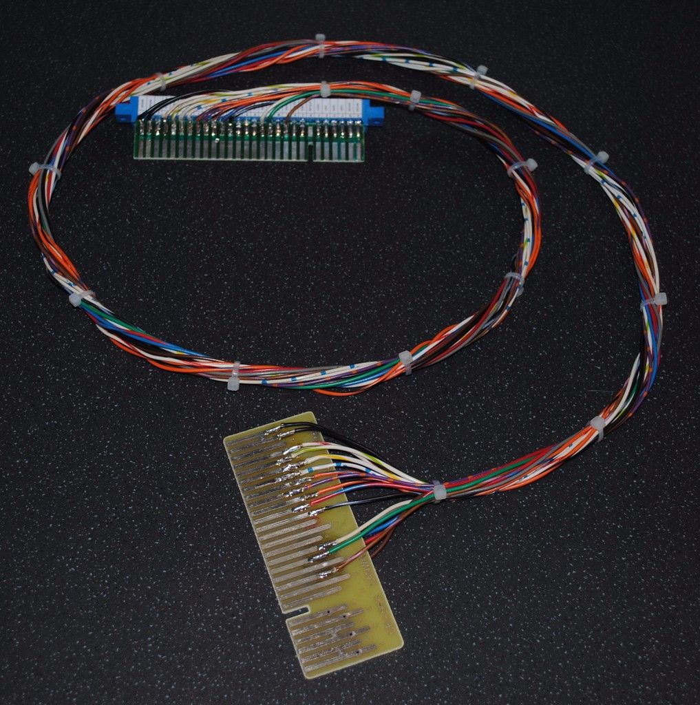
Earlier this year I made a simple little Vs loom specifically for these cabs. Annoyingly I have a bought Vs loom somewhere but I've no idea where I've safely stored it
A JAMMA edge connector, a couple of fingerboards, a few lengths of wire, cable ties

I posted this somewhere else but may as well stick it here too.
Earlier this year I made a simple little Vs loom specifically for these cabs. Annoyingly I have a bought Vs loom somewhere but I've no idea where I've safely stored it
A JAMMA edge connector, a couple of fingerboards, a few lengths of wire, cable ties


-
denson

- Please Continue...
- Posts: 517
- Joined: February 22nd, 2012, 10:36 am
- Location: Norwich, Norfolk
- eBay: chubba100
Re: Sega Dinosaur King cab - Conversion to JAMMA - Updated 31/3/16
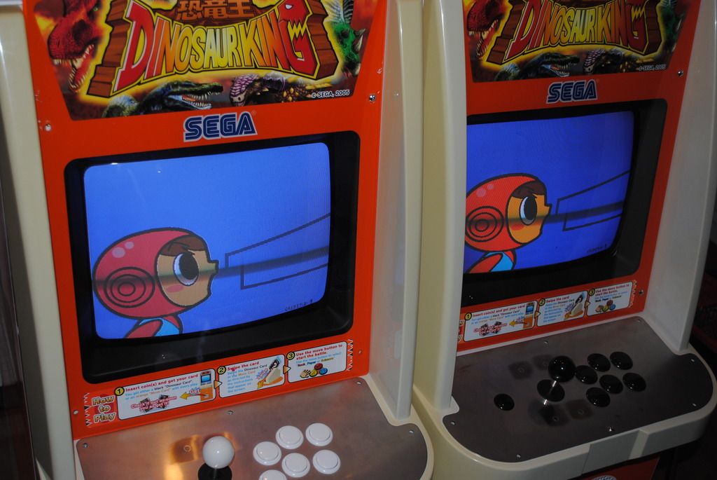
Excellent to see the two cabs linked 
Although I'm surprised you have time with your new Lindbergh sitting pretty in your games room
Although I'm surprised you have time with your new Lindbergh sitting pretty in your games room
-
Eddierang
- Please Continue...
- Posts: 90
- Joined: September 1st, 2008, 5:24 am
- Location: Houston, TX USA
Re: Sega Dinosaur King cab - Conversion to JAMMA - Updated 31/3/16
I need to find two of these cabs in the states and do the same thing.
-
Flinnster

- Please Continue...
- Posts: 332
- Joined: September 19th, 2016, 12:06 am
- Location: Surrey
- eBay: flinnster
- Initials: KID
Re: Sega Dinosaur King cab - Conversion to JAMMA - Updated 31/3/16
Interested in the vs. loom for my two
So you didn't have to do any clever video VGA connector splitting or boosting to get the same image onto both monitors? That's a lot simpler than I was anticipating!

So you didn't have to do any clever video VGA connector splitting or boosting to get the same image onto both monitors? That's a lot simpler than I was anticipating!
WTD: Rolling Thunder pcb, ANY Dino King / Love & Berry / MushiKing spare parts!!