cps2 repair method of correct voltage number

PCB problems and fixes
User avatar
kobayuz777
Please Continue...
Posts: 54
Joined: June 1st, 2018, 3:16 am
Location: japan
eBay: koba27300036

cps2 repair method of correct voltage number

Post by kobayuz777 »

It's embarrassing with simple things, please tell me. :awe:

I have CPS2 93646B-7.
The game is Aliens VS Predator.

I was thinking about repairing with Arduino because the battery was running out.
I used a 5 V power supply to connect the clip and sent the signal, but it did not work.

When measuring power with a tester connected to CN2, it was measured as 3.6V.
Was this because the PCB was loaded from 5V to 3.6 V?

If you connect the PCB to the power supply, you have to adjust so that 5V appears
Will not it be?

If the voltage is too high, the chip will break, do not you? 8-)
User avatar
NoAffinity
Posts: 386
Joined: January 8th, 2017, 3:46 pm
Location: Escondido, CA, USA
eBay: noaffinity
Initials: CSG
Contact:

Re: cps2 repair method of correct voltage number

Post by NoAffinity »

You want to measure voltage at the chips. Adjust your power supply so that the chips are getting 5V - 5.1V (5.1V max).
User avatar
nem
Needs a custom rank
Posts: 2776
Joined: August 17th, 2008, 6:59 pm
Location: Finland

Re: cps2 repair method of correct voltage number

Post by nem »

I'm not sure I follow. Are you trying to power the CPS2 with the Arduino? Because if you are, you're doing it wrong.

Put up a picture of your setup.
User avatar
kobayuz777
Please Continue...
Posts: 54
Joined: June 1st, 2018, 3:16 am
Location: japan
eBay: koba27300036

Re: cps2 repair method of correct voltage number

Post by kobayuz777 »

Measured by touching the foot of CN 2, nearby LS 245, PAL and sound ROM, it was 3.8 to 3.9 V.
Program Rom and Graphic ROM did not come out.

I'm sorry, the photo does not have time and I can not take it. I will upload it if you can do it later.
The power supply uses the used switching power supply.
I can not see it, but the noise is so large that I can not send the signal correctly?

It seems necessary to purchase a power supply with a clean 5V.
Is the display of 3.8 to 3.9 V normal before adjusting the voltage?
User avatar
NoAffinity
Posts: 386
Joined: January 8th, 2017, 3:46 pm
Location: Escondido, CA, USA
eBay: noaffinity
Initials: CSG
Contact:

Re: cps2 repair method of correct voltage number

Post by NoAffinity »

3.8 - 3.9V could be normal before adjusting the power supply. Are you able to adjust that power supply that you are using? If so, just dial it up slowly until you have a solid 5.0 - 5.1V at the chips.

Something like an arcade power supply can work well. I personally use the same power supply that is powering my super gun, with dedicated leads for powering the CPS2 board at CN2.
Image
User avatar
kobayuz777
Please Continue...
Posts: 54
Joined: June 1st, 2018, 3:16 am
Location: japan
eBay: koba27300036

Re: cps2 repair method of correct voltage number

Post by kobayuz777 »

Thank you for reply! :awe:
I can not adjust the voltage of the power supply I have now.
I think I will buy a new game power supply at auction.

↓ Is this good?
https://page.auctions.yahoo.co.jp/jp/auction/m262406618
It is 5V8A.
Is 8A too high?

By the way, is it good to use iPhone 's USB charger for Arduino' s power supply? ;)
User avatar
NoAffinity
Posts: 386
Joined: January 8th, 2017, 3:46 pm
Location: Escondido, CA, USA
eBay: noaffinity
Initials: CSG
Contact:

Re: cps2 repair method of correct voltage number

Post by NoAffinity »

If all you are doing is powering a CPS2 board for reprogrammin, 5V 8A is more than enough. You want voltage to be identical (i.e. do NOT feed the board with 12V), and amperage to be at least the minimum needed, but your power supply can be rated for more amperage than you need. The amperage rating is the maximum that the it can supply, but supplies only what the load (CPS2 board) draws from it. I don't know what the actual draw of the board is (maybe leonardo or others can chime in here), but I expect that 1A would be more than enough for simply powering the chips to reprogram the board.

If you're going to be doing other things with the power supply, like powering the board and playing via supergun, etc., then something with higher amperage rating is a better bet. Happ makes a decent power supply:

https://www.ebay.com/p/Happ-15-Amp-Swit ... 505&chn=ps

As for the arduino, it needs 7v-12v DC and 1A minimum. The plug must be center positive also. So, a 7V power supply rated at 1A, 2A, 5A, will all work, as long as the plug is center positive. A 12V power supply rated at 1A, 2A, 5A...will work. And anything in between 7V-12V, as long as the amperage rating is good and the plug is center positive.
User avatar
kobayuz777
Please Continue...
Posts: 54
Joined: June 1st, 2018, 3:16 am
Location: japan
eBay: koba27300036

Re: cps2 repair method of correct voltage number

Post by kobayuz777 »

I think that arduino can supply power by connecting USB,
Is it better to connect the center plug to supply electricity?
User avatar
NoAffinity
Posts: 386
Joined: January 8th, 2017, 3:46 pm
Location: Escondido, CA, USA
eBay: noaffinity
Initials: CSG
Contact:

Re: cps2 repair method of correct voltage number

Post by NoAffinity »

I'm not sure that there's any empirical data on this for the arduino, but in general, a dedicated wall plug is better than USB power, where you have the option.

I've seen others report that they only power their arduino via USB, and have never had a problem programming CPS2 boards. So, personal preference, I suppose.
User avatar
leonardoliveira
Please Continue...
Posts: 692
Joined: August 30th, 2012, 5:53 am
Location: Brazil
Initials: leo

Re: cps2 repair method of correct voltage number

Post by leonardoliveira »

Simplest way of reprogram keys into your CPS2 using the Arduino is have the complete CPS2 setup connected normally to a cab or supergun then have the arcade power supply or super gun power the Arduino through CN9 or CN2. No need to add extra power exclusive to the Arduino board because it's power draw is so low it doesn't even tickle the arcade/supergun power supply. That's the behavior DarkSoft's CPS2Multi exploits to achieve execution of encrypted ROMs.

On the case of early CPS2 B boards without CN9 you can simply solder the six wires to the B board or to the A board at the correct pins.

Keep in mind that CPS2 boards with CN9 the programming pins on CN2 are shorted to GND.
Image
User avatar
kobayuz777
Please Continue...
Posts: 54
Joined: June 1st, 2018, 3:16 am
Location: japan
eBay: koba27300036

Re: cps2 repair method of correct voltage number

Post by kobayuz777 »

>Simplest way of reprogram keys into your CPS2 using the Arduino
>is have the complete CPS2 setup connected normally to a cab or supergun
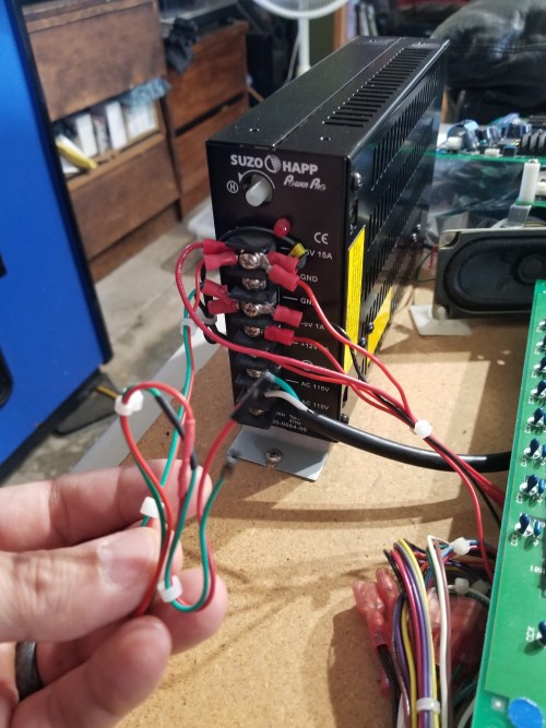
>then have the arcade power supply or super gun power the Arduino through CN9 or >CN2.

Thank you for your reply. :awe:
In the state where the control box and the A and B boards are connected (same setting as when playing the game)
Is that to reprogram by sending Arduino's signal using another arcade power supply (DC5V)?


※It is a thing of the past,
The B board of CN9 ​​was connected to the A board, and after sending the signal, it was able to repair well. :D
(Arduino connected to the USB of the personal computer and connected the power.
In the same way, sending a signal by connecting 93646B-4 to CN2 failed. :cry:

I did not know what failed.
It seems that it is in the reset state because the screen is dark.
It appears that the decryption just failed.
The B board (connected to the A board) was 3.6V when measuring the voltage with the IC pin.
I thought that voltage might be insufficient to send signals from CN2.

Since the voltage of the control box matches the settings of other games,
I do not want to adjust the voltage.

I bought an additional arcade power supply and tried repairing with B board and arcade power supply and Arduino alone.
I attempted to repair 93646B-7, but it failed.
I thought that I can not fix the initial 93646B-4 unless I can fix the board of CN9 ​​pin. :lol:
User avatar
leonardoliveira
Please Continue...
Posts: 692
Joined: August 30th, 2012, 5:53 am
Location: Brazil
Initials: leo

Re: cps2 repair method of correct voltage number

Post by leonardoliveira »

I connected my (self built) Arduino board (It was self built but is the same as Arduino UNO + shield) through flat cable to CPS2 A-Board through soldering to bottom pins of CN2 connector. That way I can program even without opening the B-Board casing. That is exactly the same way CAPCOM would program the early B boards.

Image
https://photos.app.goo.gl/1oK8Rk7cm1wNBu8x6

The key programmer stops board processing by keeping CPU halted with RESET control while key is stored. So it will instantly start operating after key programming is completed because Arduino releases CPU reset. There is no reason to believe that the B board cannot be connected to A board during programming.
Image
User avatar
leonardoliveira
Please Continue...
Posts: 692
Joined: August 30th, 2012, 5:53 am
Location: Brazil
Initials: leo

Re: cps2 repair method of correct voltage number

Post by leonardoliveira »

kobayuz777 wrote: August 28th, 2018, 9:48 am
I did not know what failed.
It seems that it is in the reset state because the screen is dark.
It appears that the decryption just failed.
The B board (connected to the A board) was 3.6V when measuring the voltage with the IC pin.
I thought that voltage might be insufficient to send signals from CN2.
I suggest you connect Razoola suicide test EPROM at socket 3 and test if doing the key programming make it stop working. Key programming makes the CPS2 CPU stop working with decrypted programs, that is the point of the suicide test rom. If the Arduino is connected wrong, key programming will have no effect and the suicide test rom will keep operating regardless.

Please let the arcade cabinet power supply power the CPS2, do not use USB port or Arduino wall power adapter because these are not powerful enough to supply power to CPS2 board set.
Image
User avatar
NoAffinity
Posts: 386
Joined: January 8th, 2017, 3:46 pm
Location: Escondido, CA, USA
eBay: noaffinity
Initials: CSG
Contact:

Re: cps2 repair method of correct voltage number

Post by NoAffinity »

I have found on occassion that programming will fail, but something gets programmed, and Razoola's suicide tester will not produce a result.

So, in the case that programming fails, or if the board is programmed with the wrong encryption key (wrong game or wrong region), the board could be suicided and non-operational, but also not testing as suicided with Razoola's tester. In this case shorting EXC1 will clear whatever is going on in the encryption controller, and the board can be confidently tested with Razoola's tester.

A best practice is to do the following before attempting to program a new encryption key: short EXC1, then use Razoola's tester to confirm the suicide tester to confirm the board is actually in a suicide state. No point wasting time attempting to program if there is some other problem. :)
User avatar
kobayuz777
Please Continue...
Posts: 54
Joined: June 1st, 2018, 3:16 am
Location: japan
eBay: koba27300036

Re: cps2 repair method of correct voltage number

Post by kobayuz777 »

To leonardoliveira

I saw pictures. This is amazing! 8-)

The flat cable seems to be connected to the A board CN2 solder side,
Although it does not seem to be taking electricity from DC jack or USB port,
Where on the A board do you connect GND and 5V?
Does the Arduino side connect from (vin terminal)?

DATA Arduino # 2 → CN2 A32
SETUP1 Arduino # 3 → CN2 A30
CLOCK Arduino # 11 → CN2 A31
SETUP2 Arduino # 12 → CN2 A29

GROUND Arduino # GND → CN2 C32 ? ? ?
+5V Arduino → ? ? ?

Repair of cps 2 is going to be quick! I also want to make this cable. :D


To NOAFFINITY

This is another suicide game (93646B-4, SSFXJ), but if you run suicide tester after shorting EXC1
This is the screen.


Although it is not displayed, the sound of the first track seems to flow.
Is not this completely cleared? :awe:
User avatar
leonardoliveira
Please Continue...
Posts: 692
Joined: August 30th, 2012, 5:53 am
Location: Brazil
Initials: leo

Re: cps2 repair method of correct voltage number

Post by leonardoliveira »

That means, since the CPU booted and sent sound code 0001 there is no key programmed. It should display video, though. Is the graphics ROMs seated properly? Is the PAL B3 seated properly? No GFX roms = blank screen.

There are pins on the C row of the connector which have power:

C-26, C-27 are GND
C-25, C-24 are +5v
Image
User avatar
kobayuz777
Please Continue...
Posts: 54
Joined: June 1st, 2018, 3:16 am
Location: japan
eBay: koba27300036

Re: cps2 repair method of correct voltage number

Post by kobayuz777 »

Graphic ROM and PAL are connected normally. Is it somewhere in a custom wire broken?

Thank you for telling me the location of the connector! I will try making it on the weekend. :)
This is connected to CN2, but in the case of B board with CN9,
Are you connecting to another place (A board)?
User avatar
leonardoliveira
Please Continue...
Posts: 692
Joined: August 30th, 2012, 5:53 am
Location: Brazil
Initials: leo

Re: cps2 repair method of correct voltage number

Post by leonardoliveira »

kobayuz777 wrote: August 29th, 2018, 11:52 pm Graphic ROM and PAL are connected normally. Is it somewhere in a custom wire broken?

Thank you for telling me the location of the connector! I will try making it on the weekend. :)
This is connected to CN2, but in the case of B board with CN9,
Are you connecting to another place (A board)?
On boards with CN9, key programming pins on CN2 are connected to GND, do not connect arduino to CN2 with these boards. Only way to program those is connect to CN9.
CN9 has pins you can use to give power to the Arduino, too.

For boards without CN9, I soldered my wires to A board connector that way I don't need to solder anything into the B board, can service B board without soldering and the programming wires do not disturb the normal operation of A board so I just ignore them when I am not using key programming.

This is how it looks like on the A-Board side:
Image
Image
User avatar
kobayuz777
Please Continue...
Posts: 54
Joined: June 1st, 2018, 3:16 am
Location: japan
eBay: koba27300036

Re: cps2 repair method of correct voltage number

Post by kobayuz777 »

Voltage supply of 93646 B-7 with a new power supply, connecting Arduino, adjusting the voltage, the board revived! :D
However, the new power supply had a limit of 5 V adjustment range.
It was 4.5 V when we measured between the pins, but it was programmed.

However, MSHJ of 93646B-4 did not resurrect. :mad:
So as leonardoliveira taught me,
I tried soldering to CN2 of board A and tried to program it,
I failed.

Image
Image

I feel like a little more. :eh:
Arduino, but there are no characters on the screen.
The screen shone blue, but the characters do not show up.
I connect VIN terminal and GND terminal to CN 2 and start up Arduino.
The board voltage was 4.6V.
Is it better to raise the voltage of the super gun (control box)?
User avatar
leonardoliveira
Please Continue...
Posts: 692
Joined: August 30th, 2012, 5:53 am
Location: Brazil
Initials: leo

Re: cps2 repair method of correct voltage number

Post by leonardoliveira »

Suicide test works with MSHJ board?
Image
Post Reply