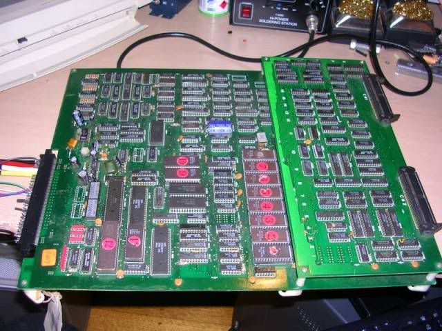
Tracks on the gfx board had been cut through with a drill, chips cut from the board and tatty bits of wire joining pins together, bits of wire badly soldered across chip legs, and chips in sockets made up out of snapped up bits of old sockets, nice single wipe jobs, guaranteed to cause troubles on old boards. One of the problems with bootlegs is that often these bodges were there from new, the PCB print may have been buggy or the bootleggers saved money by hacking another PCB design around to avoid starting a new one.
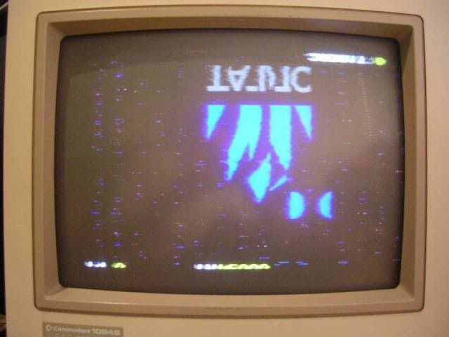
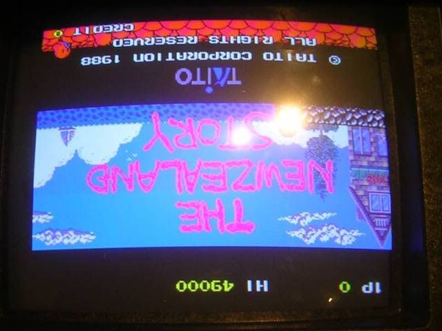
The original fault was that the board would only display a white screen, but previously it had run but the gfx were upside down and badly mangled. Well when I powered it up the board was running, but the image was all torn up, inverted and sliced up vertically too, the screen also looked like it was momentarily losing sync from time to time, this is likely to either be sync or a crappy connection to video ground. The rough edges of the image are due to the constant and violent shimmering of the image.
As the board was working I went straight for the sync signal on on the JAMMA connector and it was pretty messy on the scope. This buzzed all the way back to one of the ribbon connectors and appeared on the top board at which point it looked ok. The ribbon cable was causing the problems, multiple plug/unplug reseats on the cable fixed the shimmery issue, crappy old connectors!
The next problem was the inverted image, an original Taito board has 2 of the dip switches configured to set whether the game is in an upright cabinet or a cocktail cab and whether the image flip is on or off. The dip blocks on this board had both switched wired closed with PCB tracks, these had been cut through, probably with a screwdriver and some brute force.
When the now-active switches were closed the chopped up image came good, but the inversion remained. I spent some time looking for a fault that would cause the inversion but came up blank, finally I got confirmation from Andy at andysarcade.com that these bootlegs are hardwired to flip the screen as they do not have a working flip option, so until someone redesigns the board to read the field store in reverse, or recodes the program ROMs to fill the field store backwards the problem will remain. Both are beyond my powers anyway, I soldered wire bridges to close the dips for good again.
At this point I figured I was done, except when I moved the PCB to my cab for an upside down test play I got the dreaded white screen, moved it back to the test bench and got the same, the board would no longer boot.
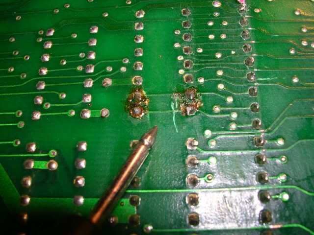
In some ways a totally crashed board is a better patient than one that is running badly, in this case I could see the signals passing through a couple of the 74ls245 chips were bloody awful, as the board was jammed the signal controlling the direction of these transceiver chips was stuck in one position, so I could easily compare the signal into the chip with that emerging on the other side, they should be pretty much identical. But
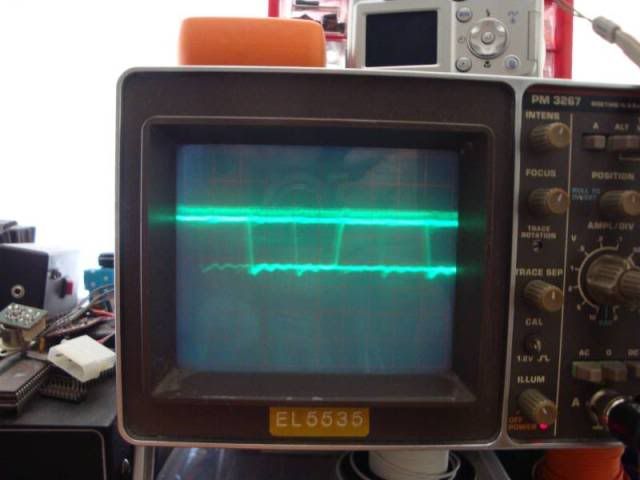
In
vs
Out
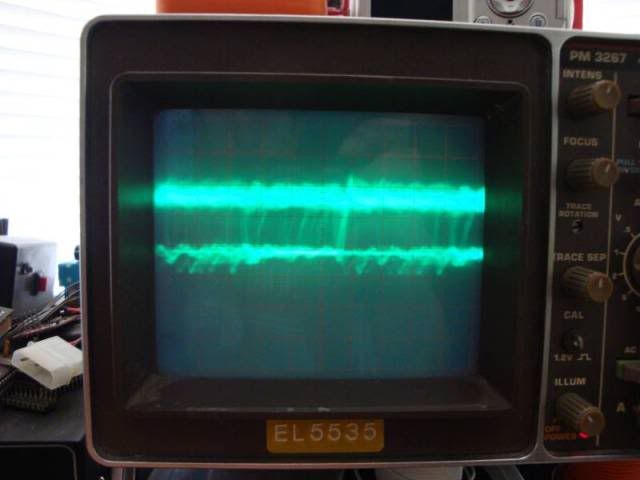
So these chips got chopped out. Normally the direction is constantly changing when the board is running so you cant really catch and "in" and the relevant "out" to compare on a normal scope.
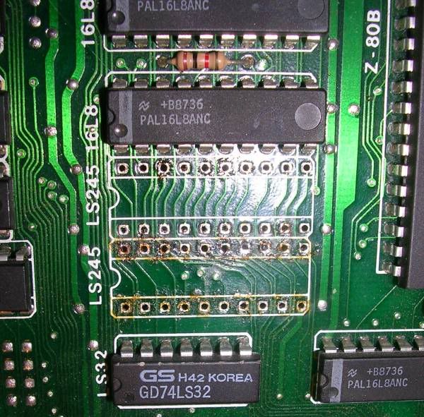
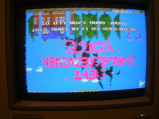
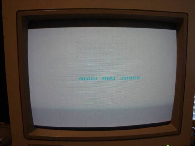
When replaced the signals were tidied up greatly. The board then booted again, for a while at least, then it gave me a white screen with "WORK RAM ERROR" written in reverse.
More scopery showed crappy signals on the data lines on the TMM2064 chips, so I desoldered one but it tested fine. Moving upstream I found a 74LS374 chip with similarly messy signals to the 245s so I replaced that chip. There are no silkscreen grid locations on the main board but the 245s and 374 are all clustered around the pair of CPUs.
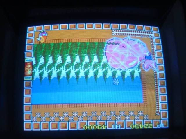
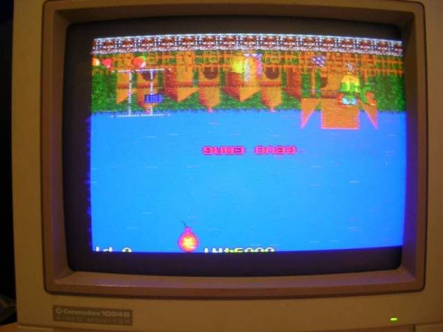
The board was now back in business, at this point it kinda wound down, the game was running, stable and pretty good. There were minor gfx artifacts that seem to be very power supply dependant and tend to fade away when the board is warmed up, but nothing really obviously wrong on the scope. The final fault was just as I was about to pack it up, I plugged it in for one last test and got a yellow screen again, this time with a very faint error message on the screen, white text on a yellow background, VDC RAM ERROR, or maybe UPC RAM ERROR (the font is somewhat hard to read), which may also mean CPU RAM error if the message is mangled. This turned out to the be the crappy ribbon cable connection again, if I had 4 new 50 way connectors I would probably have replaced them but a going over with a bud of brasso in some pliers seems to have done the trick.
That's about as far as I can go with this one...
...if I had a gun to my head on this one I probably would remove every single wipe socket on the board and replace with a machined pin, and replace the ribbon cables, this may finally remove the gfx artefacts, but with bootlegs its impossible to predict, it may not have been that great from day 1, there are a load of untestable PALs on the board and with all the hacks and patches its impossible to know what is correct and what is not. Give it a decent power supply around 5.2V and it is happy.
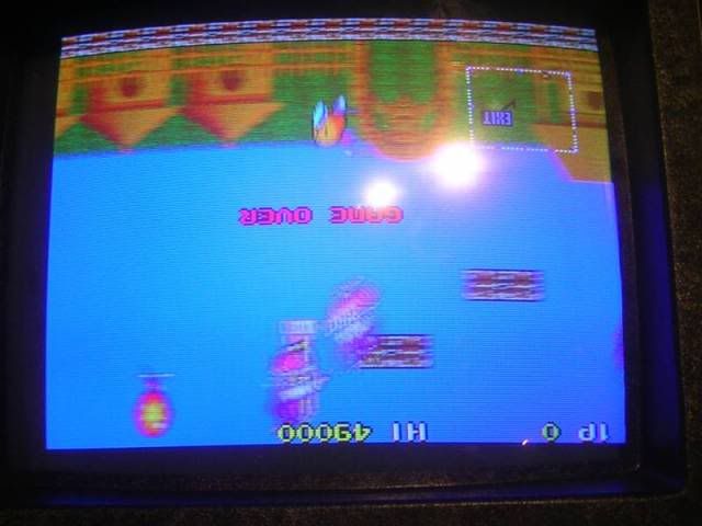
Still its now very playable again, but the feed to the vertical deflection coils in the monitor would have to be inverted to flip the screen, but its possible to through the 1st world and get to the Whale boss while upside down, but only because I know where the warps are to skip most of it