Rainbow Islands Repair Log

Fixed a PCB? Tell us how!
Forum rules
You can add Repair Logs to the Wiki here.
Womble
Please Continue...
Posts: 95
Joined: November 19th, 2009, 9:32 am
Location:

Rainbow Islands Repair Log

Post by Womble »

Been a bit dead on the old arcade front, but recently something very tasty appeared in the post...

Got a faulty original Rainbow Islands board as part of a board swap deal, I like faulty, faulty is a challenge, when powered up it gave a blank white screen and did nothing else.

Image

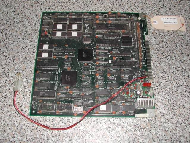
A quick visual check showed no signs of abuse, a couple of PALs had been resoldered which was a slightly concerning. There was one smoothing cap that had been wrenched to one side tearing its leg out, one of the SIP packages had been badly bent to one side and a stray ceramic cap was included as loose. From photos on the web it was clear that this ceramic cap should be strung between the ground a Vcc pins on a large Taito SPDIP chip, and there was remnants of solder on those pins so I put it back, also replaced the smoothing cap. These are really only there to fill in any ripples in the power supply and its extremely unlikely to be causing a fault on its own, the board is just less tolerant of crappy power without them. The only risk with a damaged cap is that it is shorted out internally, which is why I removed it straight off. Finally I removed the extra power cables that someone had added to the 5V and the ground pads on the jamma connector.

First port of call with a non-starter board is the CPU RESET pin, which on this board was slowly pulsing from logic low to high and back, this is the watchdog "barking". Its a small circuit that listens for activity on the CPU busses, if it sees no activity it assumes the board has crashed and issues a reset signal. This is designed to stop a crashed board sitting in a jammed state in a cab for hours and hours burning whatever image into the screen, and also to keep the coins flowing, a crashed arcade machine doesn't make much money. At this stage I dumped the eproms to check the software the board was trying to run was OK, no point looking for a hardware fault when the board is trying to run corrupt code, all the EPROMs dumped and were identical to the mame set rainbowo (Rainbow Islands Original). The mask roms are an odd pinout but they contain gfx data so would not stop the board from running, if they were bad the gfx would be a mess but the game would run.

Going round the CPU with the scope showed very little activity, the CPU was getting its clock signal but doing nothing. There were signs that the board had been wet at some stage around the CPU so I wanted to test that the CPU was OK, the only problem was that the CPU was soldered directly to the board so I removed it.

Image

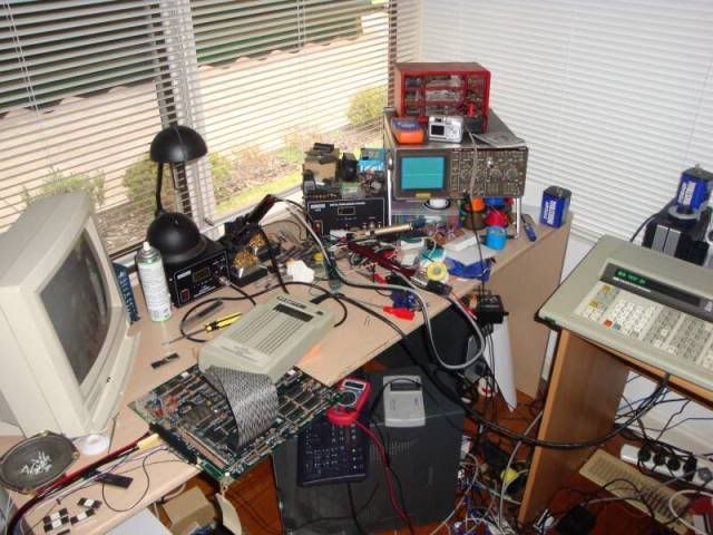
By desoldering the CPU I could test it in another board, and by fitting a socket I could wheel out the big gun, ie my Fluke 9010 and the newly arrived 68000 CPU pod. On a closed microprocessor system the CPU on the board can only run the instructions in the ROMs and has to obey all the signals given to it by the board. The Fluke 9010 with the CPU pod allows me to run various tests on the board to see what a real CPU would see, the only other way to achieve this would be to design specific ROMs for the board but as the board is faulty it may not be well enough to run any code at all.

The CPU turned out to be fine as it ran in my Golden Axe board quite happily, once I had fitted a large 64 pin CPU socket to the board I told the fluke to ignore the Reset pin, and to perform a bus test, all this does is see if it can toggle the data lines, the address lines and the IO lines. Any lines that are stuck indicate a fault with some other device on that bus, usually logic chips, RAMs and ROMs. The test passed fine, at which point I gave up for the night, the next time I fired it up the same test failed, then passed, then failed and then passed every repeat. The error reported was data lines D13 and D14 stuck.

By going over the board with the continuity tester (beep test) on my multimeter I narrowed down what was on the data bus, a bank of 4 EPROMs, 2 mask ROMs and 2 6264 SRAM chips. The EPROMs and Mask ROMs were all socketed so it was easy to rule them out, I just pulled them off the board and re-ran the Bus test, and got the same fault, so the fault was with the SRAM.

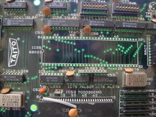
The 68000 CPU is a 16 bit CPU meaning it expects 16 bits of data for every address location it specifies. The ROMs and SRAMs were all 8 bit, meaning they have 8 data lines so when fed an address they can only spit out 8 bits. So the ROMs and RAM were wired in pairs and strung across the data bus, so ROM 10 contributes the higher 8 bits of data and ROM 11 provides the lower. Data lines D13 and D14 were therefore only on one of the chips - the Sony CXK5864-10 at location IC25. So I desoldered it and repeated the bus test, the fault never reappeared, it also helped that the chip failed the SRAM test feature on my eprom reader.

Image
The Fluke 9010 hooked up to the CPU socket with its 68000 Pod, you can just see on the main unit screen "BUS TEST OK"

I soldered in 2x14 pin sockets to make a 28 pin socket for a 6264 SRAM from a salvage board and fired the board up, same fault, white screen no activity.

At this point I went off on a tangent, having the Fluke (which I am still learning to use) gives me a huge amount of test options, the most useful being using the actual board to confirm if the CPU can read the ROMs correctly. I knew the ROMs contained the correct data, but not whether the CPU could call up and read that data correctly. The 9010 uses a ROM signature code to determine if the ROMs are readable, there is an app to generate the fluke code from the rom dumps I took from the EPROMS. If the 9010 can read the ROM contents ok it will give me the same signature code. The trouble was it didn't and this is where I spent a lot of time, firstly I had to interleave the data from a pair of EPROMs to get a 16 bit image of the ROM, ie the HI and LO bytes interleaved correctly. Once I had this file I set the 9010 to work, obviously you need to know where the ROMs actually lie within the address space, and thankfully this info is contained within the MAME driver for games.

ROM_START( rainbowo )
ROM_REGION( 0x80000, REGION_CPU1, 0 ) <----- This is the 68000 CPU section
ROM_LOAD16_BYTE( "b22-10.19", 0x00000, 0x10000, 0x3b013495 ) -- These two are interleaved
ROM_LOAD16_BYTE( "b22-11.20", 0x00001, 0x10000, 0x80041a3d ) -- when view from a 16bit CPU

ROM_LOAD16_BYTE( "b22-08.21", 0x20000, 0x10000, 0x962fb845 ) ++ These two are interleaved
ROM_LOAD16_BYTE( "b22-09.22", 0x20001, 0x10000, 0xf43efa27 ) ++ when view from a 16bit CPU

ROM_LOAD16_BYTE( "b22-03.23", 0x40000, 0x20000, 0x3ebb0fb8 ) - Mask ROM
ROM_LOAD16_BYTE( "b22-04.24", 0x40001, 0x20000, 0x91625e7f ) - Mask ROM

ROM_REGION( 0x1c000, REGION_CPU2, 0 ) <---- This is the Z80 CPU and its address space.
ROM_LOAD( "b22-14.43", 0x00000, 0x4000, 0x113c1a5b )
ROM_CONTINUE( 0x10000, 0xc000 )

So from the above I should be able to read data from address 0x0 to the end address of the ROM pair which is 0x1FFFF and get a valid signature back, except I didn't, it always came back with a differing sig code. Pointing the scope at the address and data lines while this was going on showed odd spikes, not really valid logic signals and these were always present when when the test was not running. I also noticed a distinct lack of life on the WR and OE pins on the RAM and ROMs, these tracked back to the PALs that had been resoldered, one of which had a floating output pin which I took to mean it was probably damaged, they had the original Taito part number on top but I had no idea why they had been resoldered, or even if they had been off the board. I was further discouraged by the lack of ability to get the fluke to read and sense from the RAM too.

The 9010 also has RAM test functions, again you specify an address range and tell it to go and read/write test to that address space, this test failed too. I was beginning to wonder if the 68000 pod was ok, this was the 1st non Sega system 16/18 board I had tried it on and have heard that it doesn't play nice with the Sega boards, so as I was not getting what I was expecting was either going to be due to the board fault, or a fault with the 68000 CPU pod.

The strange thing was that when I fired up a hex editor on my interleaved file and told the 9010 to get data from anywhere in the address space I always got the answer I was expecting. I tried dozens of loci and always got the right data back, right through the address space. So it looked like the board could be read but probably not at any great speed, which brought up the question of the odd spikes on the scope.

Had my desoldering iron not shat itself I probably would have desoldered the remaining Sony CXK5864 chip a lot sooner, it would have made sense seeing as its partner chip was faulty. Had a new desolder head on order from the US so I pulled the chip out as soon as it arrived.

Image

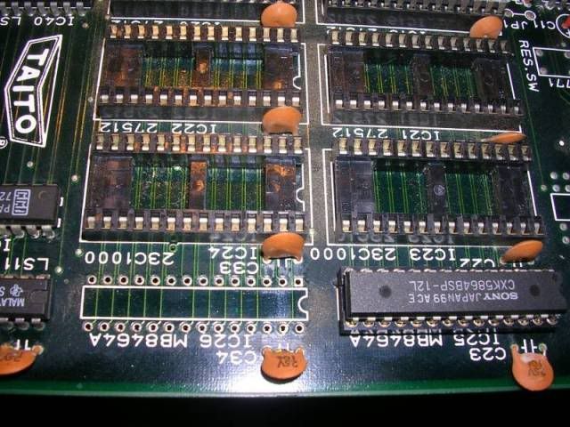
The chip tested as very faulty and also turned out to be the cause of the noise on the bus. With a another couple of 14 pin machined pin sockets on board and a new SRAM chip the board.... booted!!!!

Image

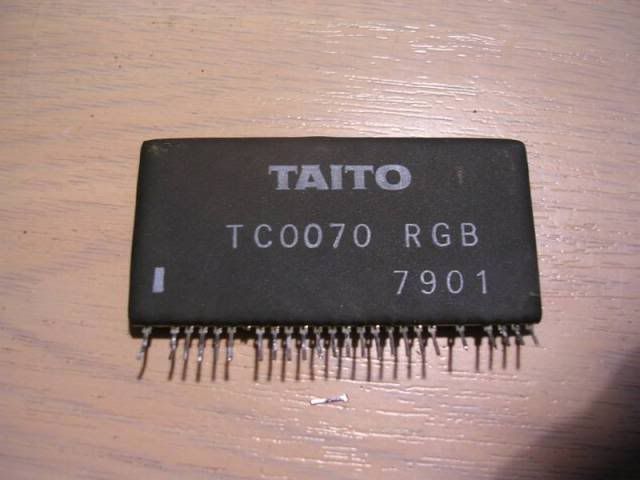
The game was up and running, but the colours were wrong, from the outset I had been concerned about a large SIP package called TC0070RGB - RBG suggesting it was involved in the colour system.

Image

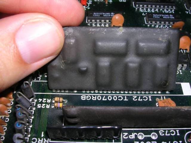
It had been pushed all the way to one side and some of the pins looked like they had been torn off. The video output was very sensitive to this chip being touched, getting far worse and or perfect from time to time.

Image

These SIP boards are very fragile and often completely missing from old boards as they get bashed off. I tried re-flowing the solder from the upper side and although this changed the fault it didn't fix it, so I had to bit the bullet and remove the SIP package in its entirety.

Image

A number of pins turned out to be totally unconnected and fell out of the board when the solder melted. In total 4 pins had not survived and as the SIP board is dual sided it looked like a number of pins only connected to onside of the board. Micro surgery time - I managed to reflow the solder on the remaining pins to bridge the gap between the two sides of the board, then had to make new legs out of LED leg cutoffs bent at the tip like hockey sticks.

Using solder as a structural material is never a good idea but in this case I had limited options, I considered mounting the SIP on a ribbon cable but I had no idea if the signals would like the extra wiring, so in the end I opted to make new legs and solder the SIP back in place.

Image

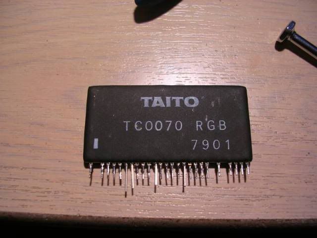
I had to use a mini file to get back to non-oxidised metal on the leg stumps and carefully soldered the LED offcuts in place. I left the new legs longer than the old ones so I knew which ones I had to be very careful and quick when soldering into the board. Once it was back in, I connected the board, flipped the switch and...

...perfect!

Image

Image

Image

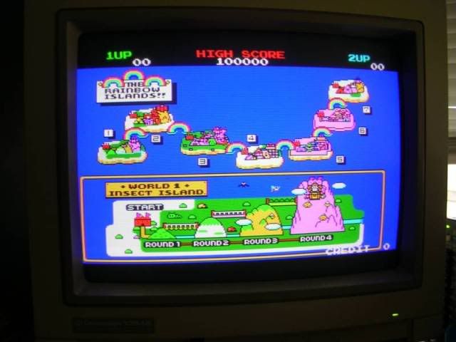
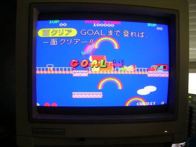
Will probably have to make a case for this PCB, that SIP colour mixer package is always going to be very very fragile, but at least she works again :)
User avatar
Rossyra
Supermod
Posts: 7902
Joined: February 12th, 2009, 1:24 am
Location: UK

Re: Rainbow Islands Repair Log

Post by Rossyra »

Great work dude, very nicely detailed write-up too :awe:
Image
User avatar
thegreathopper
Geese's Bodyguard
Posts: 1690
Joined: August 17th, 2008, 6:56 pm
Location: London
eBay: thegreathopper
Initials: STV

Re: Rainbow Islands Repair Log

Post by thegreathopper »

Excellent write up Womble, I am quite interested to know how much time in hours it took to sort the problem.
User avatar
Devil Soundwave
Doesn't go to eleven
Posts: 4713
Joined: January 7th, 2009, 11:56 pm
Location: Wetherby, Yorkshire
eBay: DevilSoundwave

Re: Rainbow Islands Repair Log

Post by Devil Soundwave »

:shock: Amazing.

Suggestion re: Sip - run hot glue along the base on either side - won't move again?

I have an original Snow Brothers which has a similarly **** hybrid. I attempted microsurgery to attach new pins as I'd seen Mr Sporty do that, but I failed miserably. Might go try again! :)
Womble
Please Continue...
Posts: 95
Joined: November 19th, 2009, 9:32 am
Location:

Re: Rainbow Islands Repair Log

Post by Womble »

thegreathopper wrote:Excellent write up Womble, I am quite interested to know how much time in hours it took to sort the problem.
Probably 10 hours all up, it sounds a lot (even to me, looking back over the repairlog) but even if the faulty chips were known at the outset it would probably take an hour or two to do the repair. As I was wandering off into lets play with the Fluke 9010 land it dragged it out further. Had I not had the fluke I would have probably fixed it in half the time but working somewhat blind, but I like to know all the stuff the 9010 lets me see.
Devil Soundwave wrote::shock: Amazing.
Suggestion re: Sip - run hot glue along the base on either side - won't move again?
Not a bad idea but its a bit permanent for my liking, if the SIP is ever damaged again it would be almost impossible to get the glue off to make a fresh repair, I get a fair few boards passing through my hands so if I come across a faulty board with that RGB SIP on it I may well replace the fragile one, if I solder it in laying down it should be fairly safe. Any other board, bootleg especially I probably would consider the hot glue option, but RI is rarer than rocking horse poo so am keen to keep it as close to original as possible.
User avatar
mastercello
Posts: 731
Joined: August 18th, 2008, 11:42 am
Location: Lucerne, Switzerland
eBay: mastercello
Initials: BUS
Contact:

Re: Rainbow Islands Repair Log

Post by mastercello »

Very nice repair log womble...congratulations on the repair :!:

These Taito RGB custom ic's are a bitch to repair, had a Volfied with a broken one once. :crazy:

Keep up the good work, i also enjoy a lot do some small repairs and modifiaction.
But it's nothing compared to your work...really. :awe:
User avatar
gargoyle67
The movie topic guy!
Posts: 5083
Joined: August 22nd, 2008, 11:33 am
Location: Clacton-On-Sea init
eBay: gargoyle1967

Re: Rainbow Islands Repair Log

Post by gargoyle67 »

Amazing job I don't have the 1st clue about repairing pcb's but I find reading about pcb repairs fascinating for some reason :think:
"Yeah lets all get ponys instead, wait no lol trendy cabs" Err I think you meant Ponies didn't you ?
VectorGlow
Posts: 505
Joined: November 8th, 2008, 11:40 pm
Location: Wales, UK
eBay: realflight

Re: Rainbow Islands Repair Log

Post by VectorGlow »

If you find it fascinating then that's a great first step to doing your own repairs. Why not give it a go? :)
Arcade game board repairer
User avatar
gargoyle67
The movie topic guy!
Posts: 5083
Joined: August 22nd, 2008, 11:33 am
Location: Clacton-On-Sea init
eBay: gargoyle1967

Re: Rainbow Islands Repair Log

Post by gargoyle67 »

Because I haven't got a clue lol
Edited should have said haven't got a clue :wtf:
Last edited by gargoyle67 on February 2nd, 2010, 11:48 am, edited 1 time in total.
"Yeah lets all get ponys instead, wait no lol trendy cabs" Err I think you meant Ponies didn't you ?
Womble
Please Continue...
Posts: 95
Joined: November 19th, 2009, 9:32 am
Location:

Re: Rainbow Islands Repair Log

Post by Womble »

VectorGlow wrote:If you find it fascinating then that's a great first step to doing your own repairs. Why not give it a go? :)
Spot on - thats how I started, I stumbled across the aussiearcade.com.au forum where there is a large section of repair logs, I just loved reading them, so I picked up a faulty TMNT board on ebay and decided I wanted to learn how to do it too. I only started 2 years ago, prior to that I could build a few electronic kits from Maplins/Jaycar and knew one end of a soldering iron from the other but not a whole lot else.

Seriously, give it a go!
User avatar
rtw
Posts: 53
Joined: August 25th, 2008, 8:44 am
Location: Norway

Re: Rainbow Islands Repair Log

Post by rtw »

Very nice and detailed writeup Womble :D

I noticed you removed the 68000 without killing it. May I ask what your technique is for removing 40 pin DIL chips and upwards ? (While not destroying them)
User avatar
Devil Soundwave
Doesn't go to eleven
Posts: 4713
Joined: January 7th, 2009, 11:56 pm
Location: Wetherby, Yorkshire
eBay: DevilSoundwave

Re: Rainbow Islands Repair Log

Post by Devil Soundwave »

Can I add this repair to the wiki please Womble?
:)
Womble
Please Continue...
Posts: 95
Joined: November 19th, 2009, 9:32 am
Location:

Re: Rainbow Islands Repair Log

Post by Womble »

Am happy for any of my posts to be wikified :)
rtw wrote:I noticed you removed the 68000 without killing it. May I ask what your technique is for removing 40 pin DIL chips and upwards ? (While not destroying them)
I have a desolder station, its like a soldering iron with a fatter hollow tip, the hollow connects back to a vacuum pump, I just go over the pins getting new solder into the joint (firstly to add flux and secondly to add more metal to conduct heat) then put the pin into the hollow, wait until I see the solder wet the leg and press the button. The pump fires up, and slurps out the solder, with some waggling and practice its possible to get the pin hanging in space in the platethrough hole, then when you do the last leg the chip comes loose. Have a fair few scrap boards which had 68000s and Z80s on them which I desoldered for my stock. A 68000 cpu takes about 5 minutes to come off from start to finish and doesnt get a roasting, the only troublesome pins are the 5V, the ground, and any control pins soldered to these planes. On most boards the tracks to the 5V and ground are either very fat or are actually large sheets of copper inside the board itself, if you hold a board up to the light you can often see what looks like a star shadow on the power pins thats the connection to the relevant plane in the multilayer board. This acts like a massive heatsink and its often impossible to get the solder to stay hot enough when you fire the pump, on some boards I have to hold the soldering iron against the leg and level the chip out while the solder is sludgy, it never gets hot enough to fully liquify.

The desolder station I got cost me about 100 quid ish, not cheap but considering the hundreds of chips I have got off scrap boards and therefore not had to buy and pay postage for its made its money back. Its also very useful to take a suspect chip off a board with its legs intact so it can be tested out of the board, thats saved many chips from being cut out of boards over the last couple of years.

This is what I use, its at the cheapy end of the scale, you can spend upwards of $1000 on a really really good one, which if you use it all day everyday would probably be worth it, I had to buy a new head end for mine as the seal and the casing started to give up.

Image
VectorGlow
Posts: 505
Joined: November 8th, 2008, 11:40 pm
Location: Wales, UK
eBay: realflight

Re: Rainbow Islands Repair Log

Post by VectorGlow »

I also have one of those. :)
Arcade game board repairer
Womble
Please Continue...
Posts: 95
Joined: November 19th, 2009, 9:32 am
Location:

Re: Rainbow Islands Repair Log

Post by Womble »

Hehe - great minds ...

Hows yours going - mine working much better after some bits replaced.
VectorGlow
Posts: 505
Joined: November 8th, 2008, 11:40 pm
Location: Wales, UK
eBay: realflight

Re: Rainbow Islands Repair Log

Post by VectorGlow »

Mine has given me all kinds of problems since I got it. TheSolderman.com has been very helpful but it's like buying a new car that you have to keep taking to the garage to be fixed every month or so - in other words, not what you hoped for when you bought it.

Latest problem is that the barrel of the iron gets way too hot after 10 mins or so, making it too hot to hold (the tip stays at the right temp though). It's out of warranty so thesolderman won't help (for free) so I just have to put up with it or splash out some non-existent cash on a new iron. I work around it, but it's a pain at times (literally!).
Arcade game board repairer
Womble
Please Continue...
Posts: 95
Joined: November 19th, 2009, 9:32 am
Location:

Re: Rainbow Islands Repair Log

Post by Womble »

Mine does get warm but it takes ages to get to the point where its noticeably hot to hold and its rarely on for that long. I think I managed to knacker the seal in the old iron head, and as a result it clogged a lot than the new one does. As it clogged I had to unscrew the 3 screws holding the head together and the screw threads finally gave out, and one of the wires feeding the element fractured, amazingly I managed to solder that back together and it stayed working. In the end I had to buy a new DIA60 head for it and its like new again.

It was very well behaved from new tho, does yours still have the insulating plate that goes between the solder tube and the switch PCB in the head?

The biggest problem is a design flaw, when you put the iron in its stand loose flecks of solder can fall back onto the inner end of the solder tip tube, its ok when its on but when you put it back in its stand and turn it off they harden and its badly blocked when you turn it back on again.
User avatar
rtw
Posts: 53
Joined: August 25th, 2008, 8:44 am
Location: Norway

Re: Rainbow Islands Repair Log

Post by rtw »

Womble wrote:I have a desolder station, its like a soldering iron with a fatter hollow tip, the hollow connects back to a vacuum pump, I just go over the pins getting new solder into the joint (firstly to add flux and secondly to add more metal to conduct heat) then put the pin into the hollow, wait until I see the solder wet the leg and press the button.
Thank you for taking the time to explain your procedure :D

Only two questions remain:

. Where did you buy it ?
. What would you buy instead ? :D
User avatar
Devil Soundwave
Doesn't go to eleven
Posts: 4713
Joined: January 7th, 2009, 11:56 pm
Location: Wetherby, Yorkshire
eBay: DevilSoundwave

Re: Rainbow Islands Repair Log

Post by Devil Soundwave »

Womble
Please Continue...
Posts: 95
Joined: November 19th, 2009, 9:32 am
Location:

Re: Rainbow Islands Repair Log

Post by Womble »

I bought mine from the local electronics store, they were in the process of getting rid of most of their tools and all of their components, they now only sell USB powered tat, laptops and mobile phones :(.

BUT - the desoldering station in the photo is re-badged under different names in different countries, mine is called a "Dick Smiths T2270", its better known as the Xytronics LF6000 I think, they are identical devices, just a different name on the front. Dick Smiths used to be what Maplins in the UK is.

What else would I buy? I would buy the same thing again actually, I haven't had any problems with it that weren't of my own making. Am pretty sure mine cost me AU$299 (about 150 quid nowadays) but came with a free T2260 which is another rebranded box, a Xytronics LF1000, actually a very good soldering iron, heats up in a flash.

http://www.howardelectronics.com/xytron ... LF1000.JPG

The "lead free" just means it gets hot enough to work with lead free solder, works fine with normal solder. Unless you plan on doing a lot of soldering/desoldering (which I seem to do these days) there is no point going for the higher end gear really, I am still getting very good service out of the bottom of the range gear anyway.
Post Reply