Fixing Naomi connectors.
Forum rules
You can add Repair Logs to the Wiki here.
You can add Repair Logs to the Wiki here.
-
KmanSweden

- KmanSweden
- Posts: 1242
- Joined: October 13th, 2010, 10:37 am
- Location: Stockholm, Sweden
- eBay: KmanSweden
- Initials: PKK
- Contact:
Fixing Naomi connectors.
I've been fixing Naomi's and DIMMs. Just wanted to show that it IS do'able.. 
Up the Irons!
-
kazuo

- Posts: 455
- Joined: November 3rd, 2008, 7:18 am
- Location: Phuket
Re: Fixing Naomi connectors.
Any tutorial for disassembling & removing the connectors? Having tons of issues with my DIMM carts and I am beginning to think it is bent pins. 
-
KmanSweden
- KmanSweden
- Posts: 1242
- Joined: October 13th, 2010, 10:37 am
- Location: Stockholm, Sweden
- eBay: KmanSweden
- Initials: PKK
- Contact:
-
KmanSweden
- KmanSweden
- Posts: 1242
- Joined: October 13th, 2010, 10:37 am
- Location: Stockholm, Sweden
- eBay: KmanSweden
- Initials: PKK
- Contact:
Re: Fixing Naomi connectors.
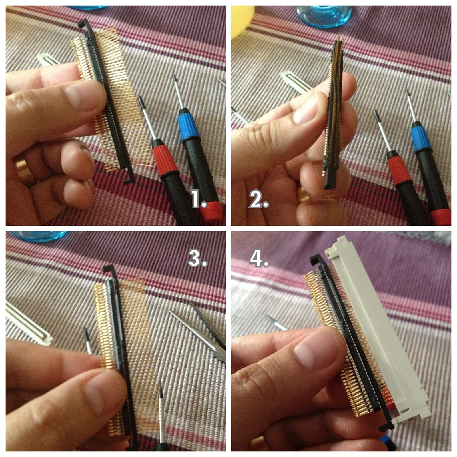
I was fixing this issue..
With two smaaaal screwdrivers insert and pry like this..
1.) Find the small hole in the connector.
2.) Insert screwdriver.
3.) Find the tab on the opposite side.
4.) Then carefully pry it out like this..
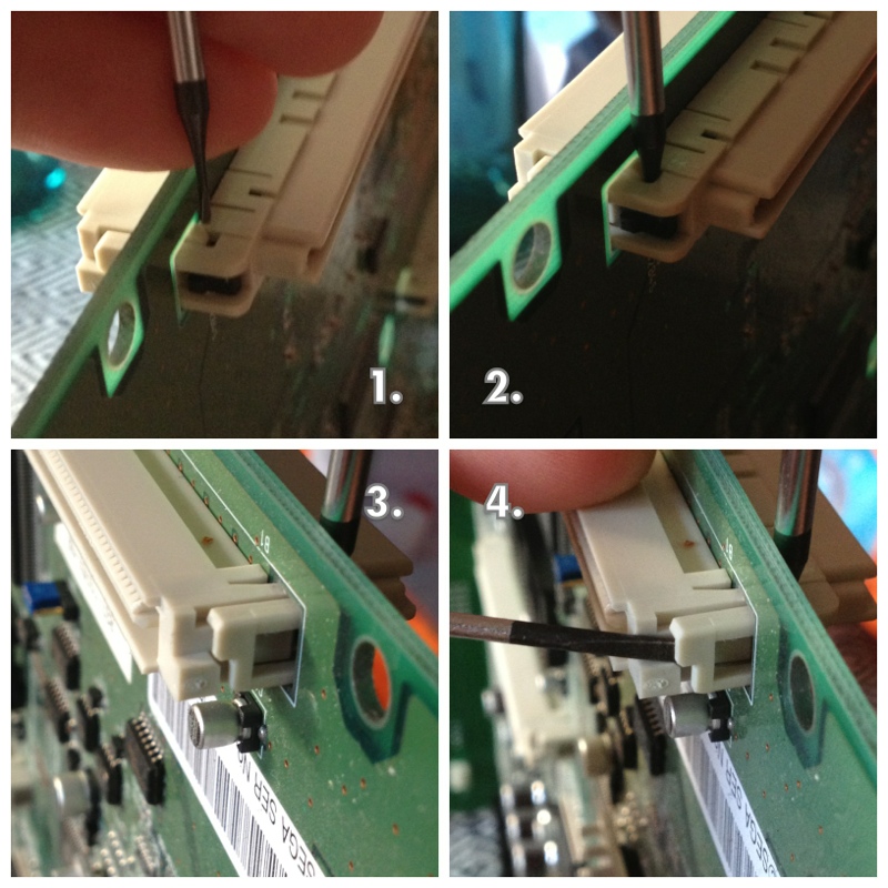
5.) At the same time pry like this on the opposite side.
6.) Repeat steps 1-5 in the other end to free the connector.
7.) Compress the small tabs and pull the connector out on the other side.
8.) Repeat on the other end of the connector and the 2nd part of the connector should be free.
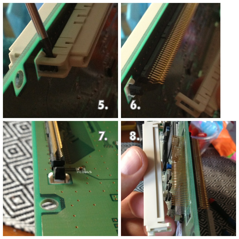
The it's all about, with one of the small, flat screwdrivers, carefully prying under the black plastic in pic 6 & 7. Start in one end and work your way to the other and then back again i small steps until you free the pins. PLEASE NOTE that it took me about an hour to put the pins back the first time..
Reassembly is just the steps in reverse but make sure you put the pins in from the correct side and that the two white plastic parts end up the right way and on the correct side of the PCB. Take pictures before you start and as you go so you don't **** up.
A good tip is that you probably won't succeed in pressing the black plastic with the pins back flush to the pcb.. As long as you get it close enough i put the white parts back on and slowly compressed them together with a vise/clamp like this..

To make the pins align is almost a chapter of it's own..
The longer pins are more forgiving but will snap if you bend them back from a too great of an angle. The pointy tips of the flat pins can also break if they don't align when you compress the connector back together again.Take your time. Be prepared to fail and re-do. You'll have to try and try again..
With two smaaaal screwdrivers insert and pry like this..
1.) Find the small hole in the connector.
2.) Insert screwdriver.
3.) Find the tab on the opposite side.
4.) Then carefully pry it out like this..
5.) At the same time pry like this on the opposite side.
6.) Repeat steps 1-5 in the other end to free the connector.
7.) Compress the small tabs and pull the connector out on the other side.
8.) Repeat on the other end of the connector and the 2nd part of the connector should be free.
The it's all about, with one of the small, flat screwdrivers, carefully prying under the black plastic in pic 6 & 7. Start in one end and work your way to the other and then back again i small steps until you free the pins. PLEASE NOTE that it took me about an hour to put the pins back the first time..
Reassembly is just the steps in reverse but make sure you put the pins in from the correct side and that the two white plastic parts end up the right way and on the correct side of the PCB. Take pictures before you start and as you go so you don't **** up.
A good tip is that you probably won't succeed in pressing the black plastic with the pins back flush to the pcb.. As long as you get it close enough i put the white parts back on and slowly compressed them together with a vise/clamp like this..
To make the pins align is almost a chapter of it's own..
The longer pins are more forgiving but will snap if you bend them back from a too great of an angle. The pointy tips of the flat pins can also break if they don't align when you compress the connector back together again.Take your time. Be prepared to fail and re-do. You'll have to try and try again..
Up the Irons!
-
KmanSweden
- KmanSweden
- Posts: 1242
- Joined: October 13th, 2010, 10:37 am
- Location: Stockholm, Sweden
- eBay: KmanSweden
- Initials: PKK
- Contact:
-
baddy

- Please Continue...
- Posts: 387
- Joined: January 28th, 2010, 12:40 am
- Location: Sweden, Stockholm
- eBay: irishfrog89
- Initials: CHI
Re: Fixing Naomi connectors.
It should've! Is this tutorial on the wiki yet?
-
guy
- Please Continue...
- Posts: 5
- Joined: May 6th, 2015, 12:21 pm
- Location: France
Re: Fixing Naomi connectors.
Very interesting, I didn't know these connectors were soldered that way.
Thanks !
Thanks !
-
mbott1701
- Please Continue...
- Posts: 2
- Joined: April 1st, 2016, 3:34 pm
- Location: Pennsylvania, United States
- eBay: mbott1864
Re: Fixing Naomi connectors.
Thanks for the info. I'm looking to replace the connectors on my Naomi board.
Do you know the specific Omron part number for the connectors? Is this it?
http://www.mouser.com/ProductDetail/Omr ... eUM0rVw%3d
Thanks.
Do you know the specific Omron part number for the connectors? Is this it?
http://www.mouser.com/ProductDetail/Omr ... eUM0rVw%3d
Thanks.
-
nem

- Needs a custom rank
- Posts: 2776
- Joined: August 17th, 2008, 6:59 pm
- Location: Finland
Re: Fixing Naomi connectors.
I had to do this to a Power Stone cart (sold to me as working  ). An absolute PITA job.