my-loom-works.jpg
Ok,
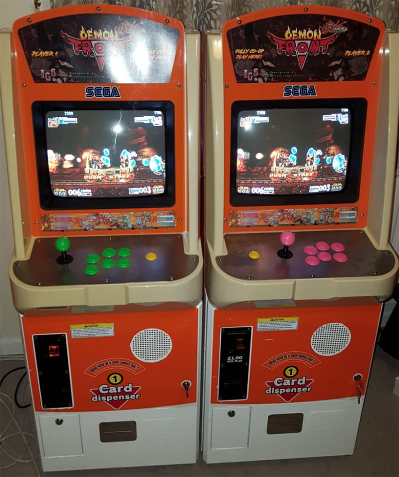
The player 1 'master' cab has the small 'passthru' jamma fingerboard plugged into the harness connector... so it has all the normal jamma edge connections for the main cab, and the game PCB can be plugged into the jamma edge on this connector as normal.
From the passthru fingerboard only cenertain wires are taken over to cab 2, which is the 'slave'. On the end of the link-loom is a fingerboard (the larger one in the photos above) to plug into cab 2's jamma connector.
- RGBS video is wired from the cab1 pins to the cab2 pins directly
- Speaker +/- is the same wired directly to the matching pins (my cabs are just mono audio)
- Ground is wired to ground on the cab2 fingerboard.
- On cab 2 'slave' fingerboard, the player 1 control pins on the parts side are wired to the player 2 controls on the solder side of the cab1 'master' passthru fingerboard.
That's the basics of it. Both my cabinets are wired 'CHAMMA' so buttons 4,5,6 are on pins 25,26, & 27 of the jamma connector.. I don't use separate kick harnesses.
You do not have the required permissions to view the files attached to this post.