The worst is done now.
No perfect but good enough.
Re: rhythm paradise naomi machine
Posted: August 16th, 2015, 2:59 pm
by KmanSweden
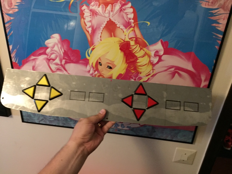
Alright. Only start buttons left to drill out.
What do you think? Should I center the buttons as on a normal panel or should I place them out in the corners? I feel that having them out of the way in the corners might be best.
Re: rhythm paradise naomi machine
Posted: August 16th, 2015, 5:24 pm
by baddy
Both seem fine really, good job so far! Some heavy filing heh?
Re: rhythm paradise naomi machine
Posted: August 16th, 2015, 9:08 pm
by KmanSweden
Drill and saw.
Re: rhythm paradise naomi machine
Posted: August 16th, 2015, 9:28 pm
by p1pkin
spmbx wrote:
andygeezer wrote:Don't expect a net boot version of this, you will need to find original cartridge, it's just not compatible with dimm boards.
What's the problem with it, just out of curiousity? The only other option apart from an original cart would be one of those cum-covered Austrian carts i presume?
the problem is - it is not known what exactly causes problem, and why decrypted&hacked game won't work via netboot.
it works fine on emulators (which isn't emulate DIMM, but cartridges only), but hang at some point then booting from DIMM at real Naomi. if you ask me - it looks like some incompatibility of this game with DIMM boards.
Re: rhythm paradise naomi machine
Posted: August 17th, 2015, 4:40 pm
by KmanSweden
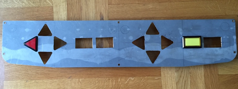
Drum roll please. It's done.
Re: rhythm paradise naomi machine
Posted: August 17th, 2015, 6:35 pm
by denson
Well done with the panel, and nice video music for showing it!
Re: rhythm paradise naomi machine
Posted: October 19th, 2017, 7:35 am
by skate323k137
I am building myself a panel for this too. Did anyone ever figure out illumination wiring? I am using the netboot version for the time being, and I'm hoping the output check is the only thing removed allowing use of type1 IO. In other words I hope the lamp drive signal is still there if I use a capable IO.
I have a type 3 sega JVS IO that I can put in my net city. I wonder if I could map it out from test mode with a multimeter if it has enough outputs.
Re: rhythm paradise naomi machine
Posted: October 19th, 2017, 8:20 am
by Shadolf
Crazy, never heard of the game. Always nice to find out about cool games that slipt through my radar
Now to hook up type 3 IO and see if I can trace illumination wiring...
Re: rhythm paradise naomi machine
Posted: October 20th, 2017, 1:28 am
by skate323k137
Type 3 IO outputs do toggle!
I didn't map them out yet but they appear in a logical order from test menu
however I don't know how to use this... they toggle between floating and ground. I.e. if I leave a probe on GND, and check the outputs, they're either floating (NC) or 0v (ground.) Should I tie that to one post on the light and put the flip side to the voltage I need? (5 or 12)? Never done these before.
Re: rhythm paradise naomi machine
Posted: October 20th, 2017, 3:30 pm
by nem
skate323k137 wrote:however I don't know how to use this... they toggle between floating and ground. I.e. if I leave a probe on GND, and check the outputs, they're either floating (NC) or 0v (ground.) Should I tie that to one post on the light and put the flip side to the voltage I need? (5 or 12)?
Yes, that's right.
Re: rhythm paradise naomi machine
Posted: October 20th, 2017, 4:40 pm
by skate323k137
Thanks! Copying my post from arcade-projects
Illumination wiring was (mostly) straightforward. I never did find a thread with it documented so I just traced it out. Thanks for reaffirming I should just run 12v to all the bulbs and then use the "outputs" for the ground connections. It makes a lot of sense actually.
First I made myself a cable to hook to the cab. One end was DB15 (to hook to the panel) with outputs 1-14 on pins 1-14 and 12v on pin 15. The other end was split to an 8 pin AMP and 20pin (AMP RA?) connector for the type 3 IO.
The net city had a female 8 pin AMP connector from the old type1. Its pinout was basically 12v on pin1, and 6 outputs on pins 2-7 (in what order, I have no idea). So basically, I wired pins 1-6 of the dsub to the amp up for that connector, as well as the 12v which I threw on pin 15. Then output pins 7-14 went to the 20 pin connector for the type 3 IO's additional outputs.
Output number wise they traced out like this (*)
1 - 1P START
2 - 1P DOWN
3 - 2P START (WTF)
4 - 1P LEFT
5 - 1P UP
6 - 1P RIGHT
-
7 - 1P A
8 - 1P B
9 - 2P UP
10 - 2P DOWN
11 - 2P LEFT
12 - 2P RIGHT
13 - 2P A
14 - 2P B
(*)I'm guessing the net city output connector for 1-6 isn't in numerical order, given outputs 7-14 are in the same order as the test menu. I just turned on one light at a time in test mode to map those out real quick.
Thankfully, it was TOTALLY WORTH IT. The lights don't do anything in attract mode, aside from light up if you push a button. But in game mode, they illuminate based on the game you're playing to show you what buttons are "legal" to press. Super helpful on new games or remix mode.