I've tried to go back to basics as possible. Let me know if I've missed anything or anything is wrong.
Many Superguns are designed to use a PC ATX PSU which is a bit of a design flaw as you cannot adjust the 5v level on most ATX PSUs which could over or under power your PCBs, which can cause them to run incorrectly or possibly even damage them. If you want to use a Supergun you should idealy power it with a switching PSU with 5v adjustment. The type using in arcade cabinets is naturally ideal.
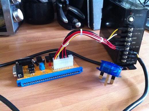
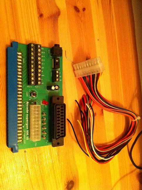
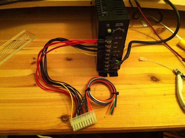
Ok, this is the Supergun, 20pin ATX cable and PSU I had to wire up:
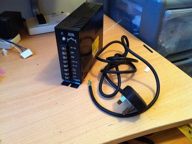
Before you start with the PSU take a look and see if there is a voltage input selector switch. Some have a 110/240v switch whereas others are auto switching. If yours has a switch then select the voltage to suit.
The first job is to wire a plug on. You want a plug with a 3A fuse and three core cable (neutral, live and earth).
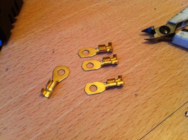
The PSU has screw terminals which is where power is input and output from the PSU. I like to use ring crimps for these terminals. You can use forked spade terminals or even just clamp bare wire but they are not ideal. Ring crimps cannot come out unless the screw comes completely out but bare wires and spade terminals can easily come out if the screw comes a little loose. Ring terminals also have a nice, large conductive area.
I like to use uninsulated crimps and then insulate them with heat shrink. I don't like the pre-insulated crimps as I tend to find they don't crimp very nicely. These are the ones I picked up. The hole in the centre is the right diameter but they are a little too wide to fit in between the terminals so I ground them down a little.
Strip and crimp your three wires coming from the plug:
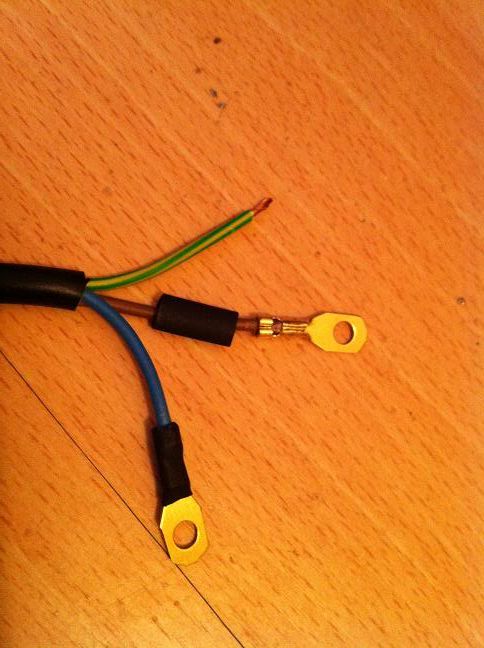
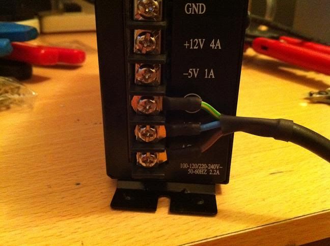
Unscrew the terminals and fasten the crimps in the right place. The green/yellow earth wire will go to the terminal with an Earth symbol or it is sometimes marked as FG (Field/Frame Ground). The blue neutral wire goes to neutral and the brown live wire goes to live. Since it is AC i don't think it matters which way round the live and neutral go, the live and neutral terminals on some PSUs are just marked AC and AC. If they are not marked then just put them either way round but I guess if they are marked then its best to wire them as directed.
At this stage I would roughly set the 5v level as you may have no idea what it is set at, especially if it's a new PSU.
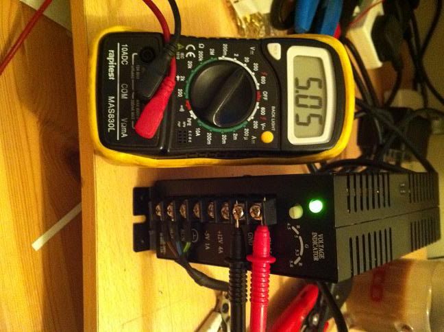
To do this, set your multimeter to measure DC voltages and to the range above the voltage level you are measuring. I'll be measuring -5v, 5v and 12v so I have set my meter to the 20vdc setting.
Turn your PSU on and then touch the black probe to one of the GND terminals and then touch the red terminal. I screwed mine into the terminals as I needed to take a photo. You should get a reading on your meter. If its outside 4.9-5.1v at this point then I would adjust it using the little white pot on the front of the PSU.
Now we can wire the ATX cable to the PSU.
[Here] is the ATX pinout. We need to connect the GND, 5v and 12v wires from the ATX cable to the PSU.
The GND wires are pins 3, 5, 7, 13, 15, 16 and 17
The 5v wires are pins 4, 6, 19 and 20
The 12v wire is pin 10.
You will notice that the wires are colour coded but trying to identify wires/voltages by colour is not a good idea as not all manufactures/companies stick to the same colour scheme. Most PC things tend to use red for 5v and yellow for 12v. Sega on the other hand use yellow for 5v and red for 12v so as you can see it can be easy to make an expensive mistake. It's also possible that someone may have wired something using any old wire, especially on used things and the wire could be be carrying any old voltage. If you are unsure always try to find a pin out and/or check the voltage with a meter or trace the wire using the continuity setting on your meter.
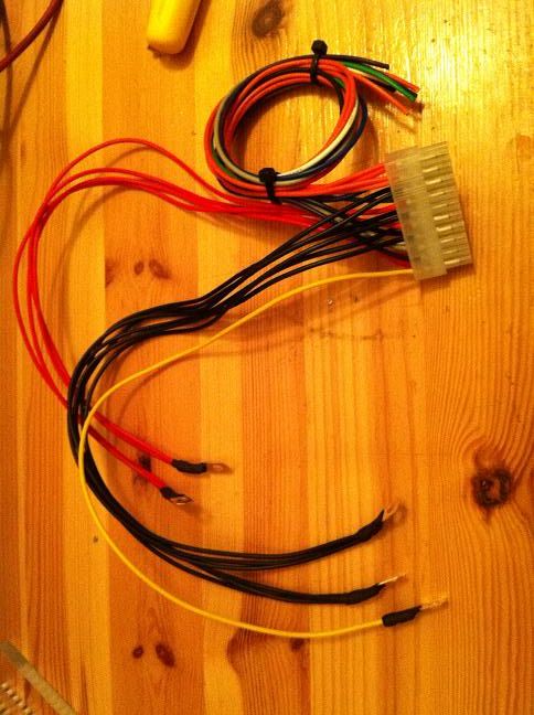
I split off six of the GND wires, all four +5v wires and the single 12v wire. You want to wire as many of the wires as possible to the PSU to give plenty of wire for the current to flow down. It's much better to use multiple wires then to use a single wire. Using multiple wires will lower the resistance in the wires and the 5v level is more likely to stay closer to what it is set at at the PSU.
Crimp the wires and terminate them at the PSU:
Another thing I did was to solder a wire to the supergun to feed -5v to the JAMMA edge. ATX PSUs don't output -5v and so you cannot wire it to the 20pin header. Instead I soldered a wire to pin 5 (-5v) at the JAMMA edge and crimped a bullet connector to it:
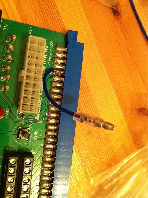
I crimped the mating bullet on another wire and then ran this to the -5v terminal on the PSU.
Before you plug any PCBs into your supergun it's a good idea to check you have the right voltages at the right places at the edge connector.
There is a JAMMA pin out [here]
I have marked the voltages on this picture that you should expect to be getting at the JAMMA edge.
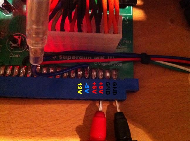
Using your multimeter again, check the voltages at those point. Keep the black probe at the GND and check the 5v, -5v and 12v. I normally touch the solder points on the PCB but I inserted the probes into the JAMMA edge as I was taking photos. You can't do this when measuring voltages on PCBs as the board will be plugged in here.
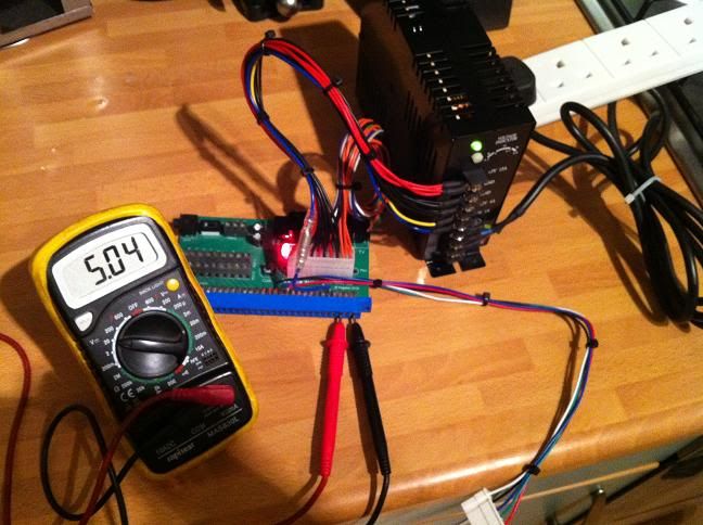
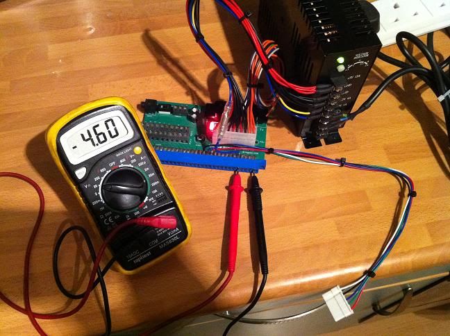
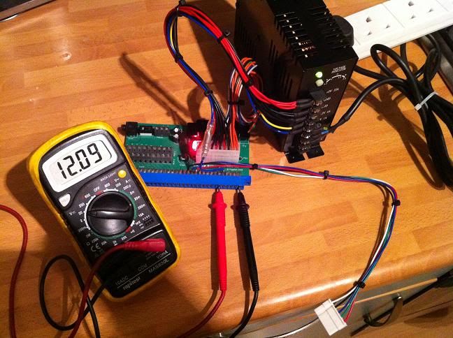
Your 5v should still be somewhere near 5v. The -5v and 12v may be a little off but this is not a problem as the -5v and 12v circuits do not need at such an exact level as the 5v.
If everything is good at this stage then you should be good to switch off and plug a game board in. Once you power up again its a good idea to check the voltage again as it will most likely have dropped a little due to the load on the PSU from the game board.
There is further reading on setting voltages [here].
EDIT:
Since writing this I have found out that older ATX PSU's may output -5v. Pin 20 (formerly −5 V, white wire) is absent in current power supplies; it was optional in ATX and ATX12V ver. 1.2, and deleted as of ver. 1.3
If your supergun has continuity between pin 20 of the power input and pins E/5 at the JAMMA edge then you can wire the -5v to pin 20 instead of wiring it to the supergun like I did above.