Anyway I very nearly made things worse for it, the edge connector looked very much like JAMMA, a quick eyeball showed the 5V lines and the ground lines where they should be. As I had bought a couple of boards at the same time I hadn't got round to plugging this one in and was idly looking for a decent PCB picture while at work. All I found was an image from someone selling the JAMMA adaptor for it, it aint JAMMA after all, its "capcom classic" pinout. I could very easily see this board being plugged into a JAMMA cab and left to fry, not very encouraging. After I made up a harness for it and powered it up I was presented with a frozen screen of crap and no sound.
A quick check proved that the voltages were ok so I moved on and hit the Z80s with the scope, both Z80s were activate, ie the reset pins were logic high (i.e. not reset), the main Z80 had a healthy clock signal on pin 6, but the sound Z80 had no clock signal at all. Ignoring the sound CPU for the time being I moved on and dumped all the PROMs, WinROMIdent was happy with all of them bar the TMM24256 ( the PROM version of a 27C256) at U13, so I burnt a copy of the rom from the MAME set and dropped it in.
No change, still got a screen full of crap, at this point I decided there was little point wasting time tracking down each rusted track the hard way so I went along the rusty edge and repaired a handful of totally rusted out tracks and vias. The neatest way I have found to fix a rusted out via is to drill it out and insert some stiff wire (component leg offcuts are good) and bend it into a U shape with each side lying along the track. Then scratch the lacquer away from the track to expose copper, tin both sides and solder the wire in place, its very neat and often hard to spot.
This didn't improve anything at this stage which was annoying but I was going to have to fix them all sooner or later anyway.
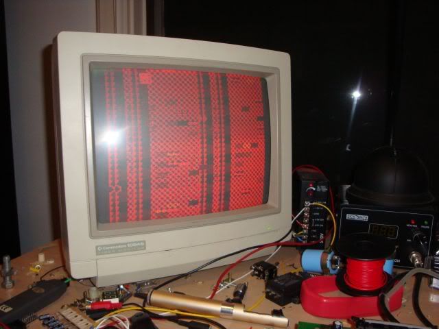
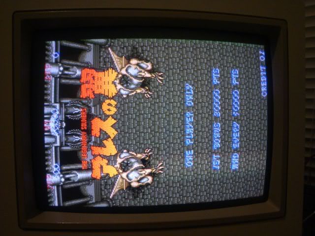
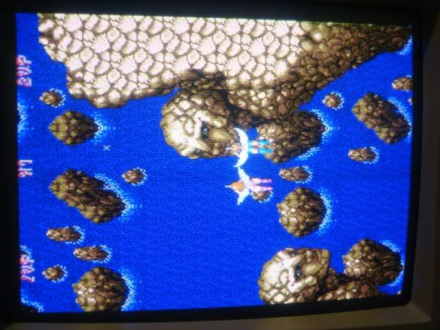
So I moved on and started to probe round the CPU with the scope, there was very little life anywhere but de-soldering Z80s takes a while so I was putting it off, the Z80 got steadily hotter and hotter until it was very clear it was borked. I dropped the Z80 into my Galaxians board which is my defacto Z80 tester these days, it too gave me a screen full of crap proving the Z80 was very dead. I fitted a socket to the board and dropped in a known good 8Mhz Z80, the game booted to a corrupt splash screen.
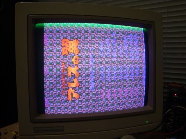
The background is clearly mangled, the same block repeated over and over again (common effect with dead graphics RAM chips), the screen is rather purple (i.e. missing the green signal) and there was a thick green smear across the top of the screen so at least there was green somewhere. The game would eventually start its attract mode, a second mangled screen would appear and would scroll along it to the start point of the level, at which point the game would crash and reset. Judging by what MAME does with this game it suggested the game was crashing as soon as it tried to display the sprites.
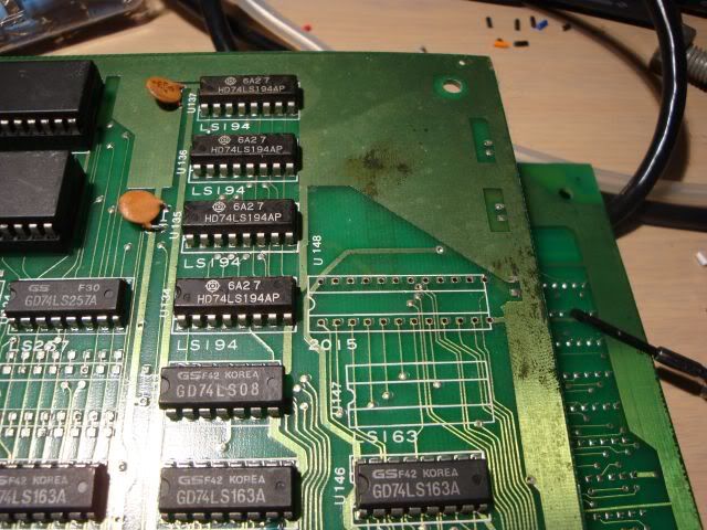
This board as per most Capcom boards of this era it is actually two boards, the CPU board and the video board. As the game was running and I was left with graphics problems I pointed the scope at the RAM on the gfx board. Both TMM2015s at U142 and U148 showed outputs held high on A3-A7, the address lines looked ok but everything on this board looked pretty nasty, the +5 was pretty unstable. This board had a number of unpopulated pads for capacitors strung between 5V and ground, to get some stability I fitted 220uF 16V electrolytic, the cap actually came from a smashed TV by the I found by the railway line while walking the dog. Had totally run out of 220uFs so I took some wire cutters with me and cut the board free from the wreckage. It tested fine on my ESR meter and the capacitance meter so I soldered it in, the voltage was now rock solid and the jumpiness was gone from all signals which was very useful.
I de-soldered both SRAM chips...
..and put them through my VP280 which can test SRAM chips, Wellei are slowly backfilling the chip database for these devices, when I 1st got it the software didnt know about any TMM201x chips, now it knows about TMM2016 and TMM2018, but not TMM2015. Not that it matters as all of them are pin for pin compatible with 6116 chips anyway. It would be an easy way for them to increase the brag count for their devices, just add all the chip names for the compatible devices and point them to the 6116 script.
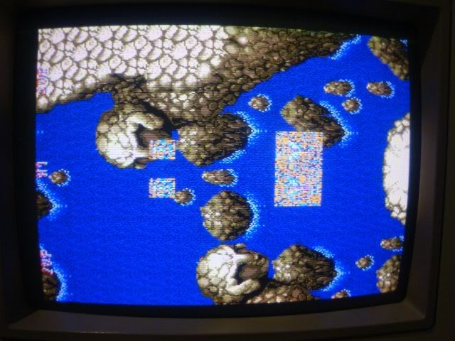
Anyway - I fitted sockets and powered the board up with them empty, I always do this to see what the effect is, it also lets me take a look at the naked data and address lines, handy to see if there is anything else on the bus. I was expecting the corrupted background to be totally missing, what I was not expecting was this...
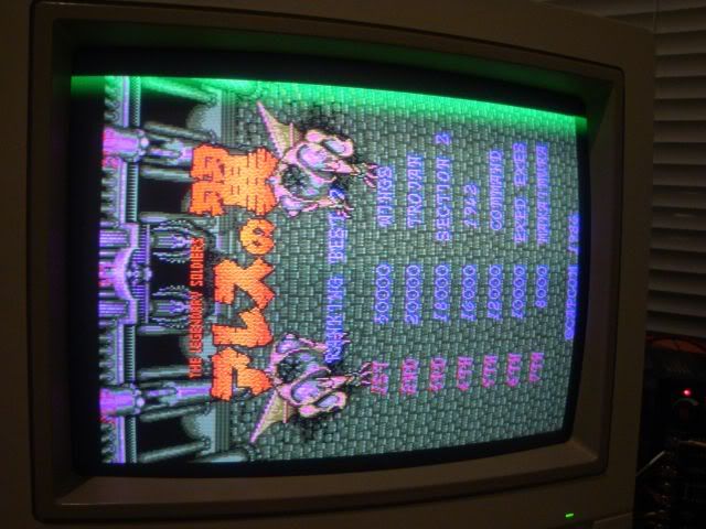
... the background was back! Usually when you take something off a board you expect to lose some functionality too, except in this case the original chips were breaking something else with their presence. When salvaged chips from a scrap board were fitted I got the sprites back, except they were blocks of corruption.
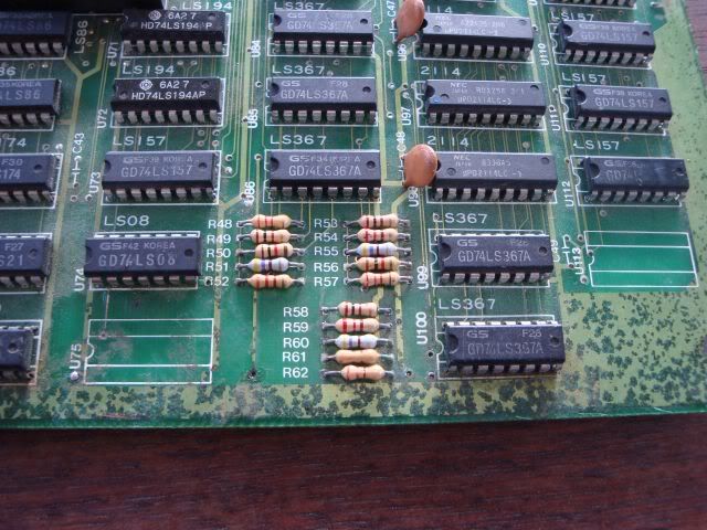
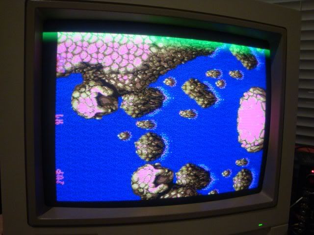
Aside from the messy sprites the gfx were still not quite right, things were odd colours and there was a green smear along the top of the screen, in fact this was all the green from the screen. The JAMMA edge RGB signals connect back to 3 blocks of 5 resistors R48 to R62. Tracing back from the JAMMA connector I could tell that R58 to 62 was the green resistor network and it was the one right on the rusty edge.
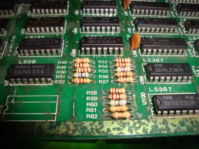
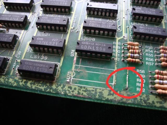
The corrosion was so bad that even though the tracks were all intact I could not get a continuity beep on many of them. Some I could get a connection to by re-flowing the soldered joints but on many this was just a blob or rust, it also made it impossible to test the resistors on the board. So with some difficulty I took them off and unfortunately they all tested fine, had to rebuild the common side of the resistors once they were reinstalled as the board is a wreck by this edge and the rusty track hadn't survived the removal process. The upshot of all this was it was a waste of time, the resistors were fine and everything had been connected up correctly. The 5 inputs to this resistor network all came from a 74LS367 at U100, of the 5 outputs only 4 were active.
It had no output on pin 9 despite input on pin 10, messing up the G signal on pin one activated this gate, this suggested that the gate was OK but the activation signal G on pin1 was missing something that was very time critical, without it the gate for pins 9 and 10 was not being activated, time to plough upstream through the logic looking for something smelly, half the reason TTL logic circuits are so resilient is that even if one chip is dodgy but still just in spec the next chip is only controlled by that dodgy signal, the outputs of the second chip are nice and clean, this does mean that something smelly doesnt make it beyond the problem chip.
The following is built from the notes I made as I was going over the board trying to find what was connected to what, a schematic would have been very useful, without it I was force to set my multimeter to continuity beeper mode, hold one probe on the chip pin and swipe the other along the all the chips on the board waiting for a beep, this will show when one is connected but unfortunately is no help when you have broken tracks - a distinct possibility on a rusty board, anyway the following padded out notes show the process, and its not fun.
Pin 1 connected to pin 6 (Q) on LS74 at U95. D pin 2 is rather quiet, traces to Q on pin 9. D pin 12 looks quiet, traces to pin 2 on LS00 at U93. Pin 3 of this chip is providing clock to U5. Pin 1 rather quiet, traces across board to LS112 at U63's pin 6. Pin 6 is output of a gate that has 5 inputs, 1 is clock that when interrupted messes up sync, two are activation signals that are tied high by the board which leaves the 2 data inputs on pin 2 and 3, these trace back to the output of the AND gates on LS08 at U51. Pin 3 goes to pin 8 and when interrupted puts jail bars on the screen, pin 2 goes to LS08 pin 11, one of the inputs is low and when interrupted it smears the screen colours..
Input one of that gate goes to edge connector and off to the GFGX board to U87/88 pin 10, also pin 11 U96 and pin 9 U9, ALL input pins - **** - back track to CPU board. I hadn't got a beep before for some reason by it also also goes to pin 11 U40 an LS161. The led me right to the fault, signals in this area looked sick due to a 74LS245 at U41 Replaced this and the fault was gone, the green is now correctly drawn and things are the right colour finally.
Had had enough of graphics faults so I attacked the sound issue next. The board was silent, totally silent, no amp buzz at all. Often this means the amp chip is dead, but in this case as I was poking around the amp chip I found a cap that was very wobbly. Someone in the past had replaced this cap and had drilled out the plate through hole before attempting to refit the cap, this left the cap leg literally nothing to connect to as the connecting track was on the upper side of the board. The cap was soldered to thin air and as it is the capacitor that sits in the signal path between the amp output and the speaker input meant whatever the amp was outputting was never going to get to a speaker. As there was nothing left to solder the cap to I had to scratch away the lacquer and solder it to the upper side of the board.
This gave me the amp chip buzz and as the volume pot changed the volume of the buzz I could rule out the amp chip.
The sound Z80 still stone cold, the board had been on for an hour or more but its conceivable that this might be normal for a Z80 without a clock signal, all the CPU outputs either high or low, again without a clock the chip will do nothing. The clock signal track was one of the tracks I repaired earlier, but a rusted out plate through hole was still not connected to track on the underside of board at a pad downstream of my blanket fixes earlier. Scraped the lacquer away and tinned track and soldered in some wire to join the two, clock signal now reached the Z80. It still remained cold to touch after prolonged power up time, so I de-soldered it and tested it in Galaxians which proved the Z80 was dead.
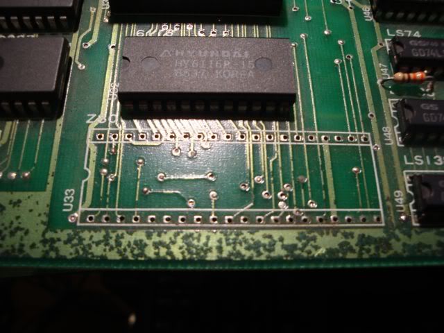
By the way, I always take photos of what is under a chip when I de-solder it, its very useful to know where the tracks go later on when there is a socket in the way.
Fitted socket and a new Z80, address lines all lit up, still no sound. All address lines traced through to 6116 RAM and were active but all data lines were held low as the CS pin was held high (chip is de-activated). The CS traced to pin 3 (Y0) LS139 (U62), right on rusted edge. My logic comparator said the 74LS139 is ok. Pin one G1 is high, all outputs will be H when G is high, only change can occur when G goes low. G traces to pin 9 (Y6) of U48 an LS138. I traced the logic around a bit but ended up going round in circles getting nowhere so I gave up and de-soldered the 6116, both to test it and to allow me to fit a socket so I could bend the CS pin out of the way when refitting the chip - the chip tested as fine and I proved it was the board holding the CS pin high and not the chip itself.
I had proven a lot of the circuit was ok, RAM was good, ROM was good, CPU was new, without a schematic it is quite hard to work out the dependencies of a circuit, had already dug into the logic of what was controlling CS without getting anywhere. Moved on to the YM2033 chips that are the sound generators, have had boards before where these were toasted as a pair and judging by the damage elsewhere on the board I was expecting these to be blown. Probing around with the scope I could see very little activity, both were also deselected as their CS pins were high - not common to the 6116 CS tho. Decided to de-solder both YMs and test them on my 1943 board that came with 2 blown 2203s, the new ones are socketed so the board makes a very good YM2203 tester. Both YMs worked fine on 1943, so I went back to the board and dumped the sound EPROM again, it was perfect, so I retested the 6116 ram, again perfect. With both the RAM and the ROM off the board I had a look at the CPU, nothing out of the ordinary, the D0 line was a bit wobbly whereas all other D lines were low, so I swapped the sound Z80 into the main Z80 socket and the board booted, CPU therefore also fine. Put the RAM, ROM and CPU back on the board and fired it up, CS on the RAM was now happily active so I fitted a pair of 40 pin sockets and dropped the 1943 YM2033s in - the sound was fine - weird!!
I swapped the pairs of YMs back so the board had its original pair in again and again the sound was fine - what the ****? I even swapped them over as a pair but the sound still worked. The only thing I could think of is perhaps the original ROM socket is dodgy but it looked mint, contacts very shiny tho. This may have to remain a mystery, unless the fault reappears there isn't much I can do to track it down, no fault = no evidence.
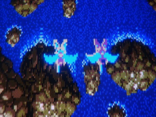
The final problem was the sprites, which were blocks of corruption.
Went back to poking around the video board, nothing seemed to be wrong tho, started off looking at the logic around the 2015s I replaced earlier, everything looked ok, the untouched 6116 caused the background to break up when interrupted so I ruled that out. There were a few old repairs in the rough area I was looking at but these were all sensible and fixed track damage so I left them alone. Went back to the source of the data - the ROMs, I had dumped and compared them all at the outset and they all tested as OK, so as the fault looked very much like an address line problem I went along the ROMs interrupting the address lines to see which of the graphics ROMs did what, the first 8 in the block caused issues with the background when disturbed so I was left with the remaining 4. I started out by pulling U111 and U112 out and booting up the board, the sprites were much improved, the outline was correct and all the corruption was absent.
It occurred to me that perhaps I had put them back reversed, or a previous owner had, as none of the chips were labelled, so I swapped them over but got the same problem. With both chips off again I booted the board and hit the address lines with the scope, they all looked active, one of them looked a bit regular, more like a clock signal than an address line but I didn't think it was that odd looking to be a fault. Divide and conquer as they say, so I put U111 back in and left U112 on the bench - the spites got even better, some colour and detail was back. That left U112 and as ROMs are usually controlled in pairs it seemed more likely that the chip was bad as the same address and data bus would be involved for both U111 and U112. The WE,OE and WR lines could be duff for U112 but it made sense to double check the ROM again, fired up the reader, dumped the rom, threw it at WinROMIdent and it was not recognised!!! This is the same chip that had read and tested as perfect when I first started with this board, I even still had the ROM dump file for U112 on the desktop. So I burnt the data from this dump into a new 27C256 chip and bingo - the sprites were perfect, board fixed!!

She's good to go, uphill struggle all the way tho.