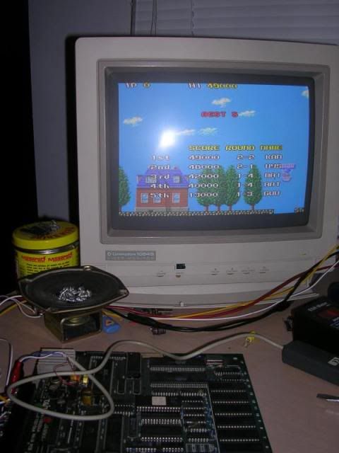
The board was constantly rebooting and coming up with a SUB CPU ERROR message.
YouTube- Faulty Arcade PCB - The New Zealand Story
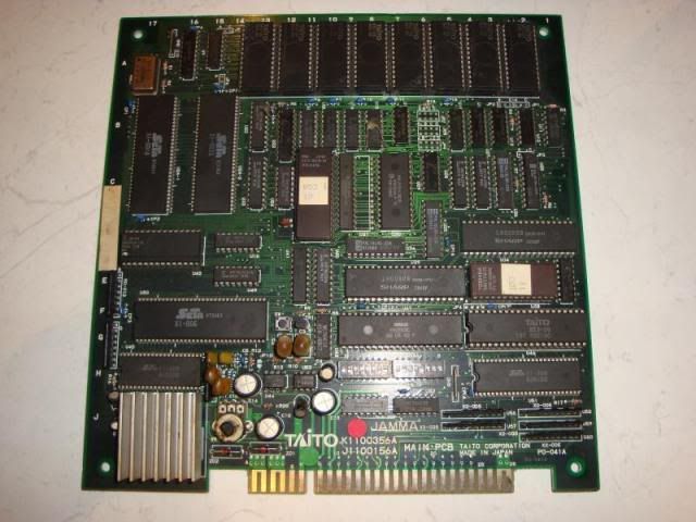
There are only two EPROMs on the board, and a load of mask ROMs that probably contain sound and gfx data (usually the game program was held in EPROMs so bugs could be fixed, gfx and sound data was unlikely ever to be changed.) So to rule out a software issue I dumped and compared the two EPROMs to the MAME set, they were fine, so it looked like a hardware problem.
The constant rebooting was due to the watchdog system that resets the CPUs if it sees no activity on the buses, this stops the boards spending hours in a hung state in a cab somewhere, the only problem is that if the fault doesnt clear the system will reset endlessly. When the watchdog is barking it is very hard to see what is going on as everything is constantly bouncing, so I went looking for a jumper to stop the watchdog from resetting the system. Original board often have one to aid troubleshooting and this board is very well made, it even has 2 raised ground loop rails to attach the scope probe to. Often this jumper is marked JP1 and is usually located very close to the reset button, if there is one. This board does have a reset button and the jumper nearest to it stops the watchdog, its called JP10 on TNZS boards though. To be as neat as possible I didnt solder the jumper pads together, I buzzed the pads back to nearby component legs and soldered a loop of hookup wire between the legs, almost invisible when removed.
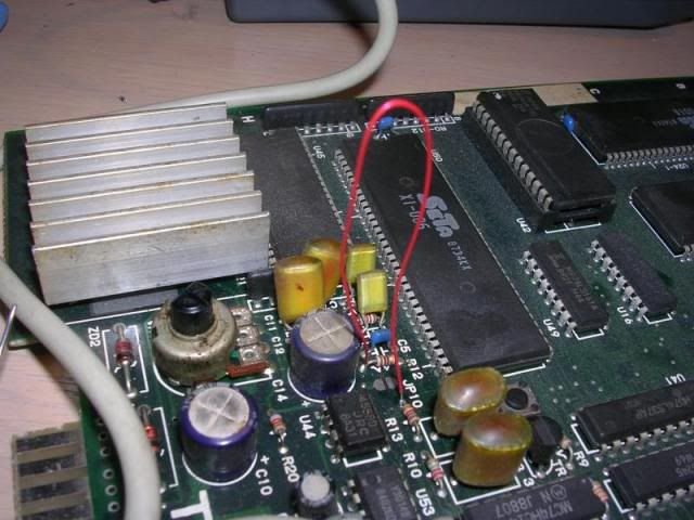
This shut the watchdog up and left the board stable displaying the "SUB CPU ERROR" message consistently. With everything stable I could go round the RAM chips with the scope, a couple of lines didnt look too healthy but as the board had presumably crashed that is not that uncommon.
The board does have a few of the dreaded Fujitsu TTL chips on it, 245s, 157s and 161s, and going over the 245s I found something odd at U27. The 245s are octal bus transceiver chips, that can allow data to pass from one side to the other, or visa versa, or they can isolate the two sides. The Enable pin was logic high which isolates the bus, so the 5V side of the chip had floating outputs, which was normal, the input side had 6 inputs that were healthy, but A3 and A4 were tied high, now this could be normal if the bytes of data banging up against the chip always had 1's at bit 3 and 4, but its not that likely, knowing the way Fujitsu chips die it was more likely that these pins had just got stuck, and the chip was no longer able to pull the outputs down to logic 0.
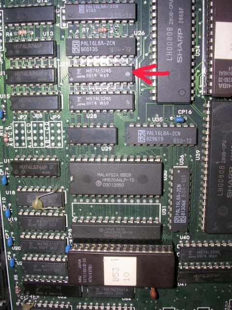
So I piggy backed a new 74LS245 chip on to the existing chip and hit the reset button.
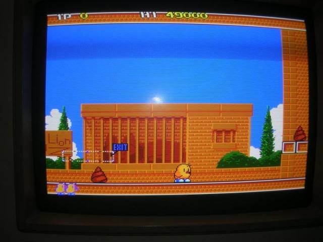
Desoldered the dodgy chip and fitted a new TI brand one to complete the fix.
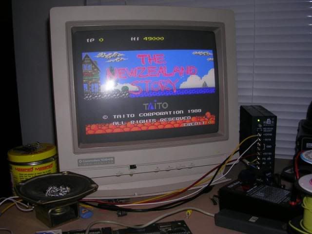
Bloody love this game!!! Is it wrong to own 2 PCBs?