Hey guys. I was reading a post earlier this week regarding a monitor. Completely different issue than the question I want to ask... but at the same time completely related.
I'm trying to use a sega model 3 monitor with one of my JAMMA games. I've already moved the monitor into the new cabinet but am now having issues trying to figure out the pinout, and want to wire the JAMMA harness into the CN 202 slot on the neck board.
Some details.
I've got the wires going from the JAMMA harness into the 9 pin connector that I put into the CN 202 slot on the neck board.
Aside from that, it was just the monitor I got, none of the other connectors or boards.
I read on the original post I mentioned that the previous owner of a similar monitor had it wired up via the CN 202 connector... so I assume it's possible.
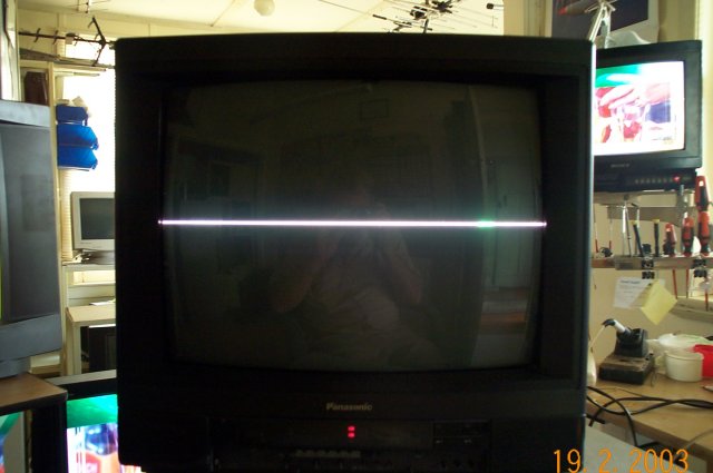
I have been able to get a signal, or... a single line across the screen, so to speak.
What I'm asking is does anyone know the pin-out of the CN 202 connector?
The red, green, blue... etc.
I've played with so man combinations, and got so many results, but I thought if anyone had the exact pinout combination... that would save so much time.
So... CN 202, nine pin connector.
Any help would be amazing.
CN 202 pinout on neck board.
-
billyC

- Please Continue...
- Posts: 12
- Joined: August 9th, 2016, 1:38 pm
- Location: Canada
-
Asayuki

- Please Continue...
- Posts: 431
- Joined: August 29th, 2015, 10:16 pm
- Location: Remuria, Germany
Re: CN 202 pinout on neck board.
Something like this?billyC wrote:I have been able to get a signal, or... a single line across the screen, so to speak.
Which monitor brand and model is that?billyC wrote:What I'm asking is does anyone know the pin-out of the CN 202 connector?
I've played with so man combinations, and got so many results, but I thought if anyone had the exact pinout combination... that would save so much time.
Did you rewire it to 15kHz mode as required by Jamma before trying?
About the pinout you can identify ground via ohm metering. RGB inputs typically have 1kohm or 75ohm terminators; again, ohm meter is your friend. The only missing wire would be sync, which probably has ESD protection diodes which you can again meter.
My 15kHz cabinet Peplos will never power up, with any item, and I am quite proud of that.
-
RMRM

- Posts: 514
- Joined: April 20th, 2013, 4:45 pm
- Location: Portugal
Re: CN 202 pinout on neck board.
There is no such thing as a "Sega Model 3 Monitor", you need to know the chassis model, but i will assume it might be a Nanao MS9 because it was equipped in different dedicated cabinets with Sega model 3.
As Asayuki said, you need to make sure the 15khz option is selected because it was probably set to 24Khx instead, if this is the case you must move the jumper to the corrresponding connector.
But first you need to identify the chassis model
As Asayuki said, you need to make sure the 15khz option is selected because it was probably set to 24Khx instead, if this is the case you must move the jumper to the corrresponding connector.
But first you need to identify the chassis model
-
billyC
- Please Continue...
- Posts: 12
- Joined: August 9th, 2016, 1:38 pm
- Location: Canada
Re: CN 202 pinout on neck board.
Hey Asayuki, that's pretty much it, in the picture. I can change the color of the line by swapping the RGB leads, and I can also make the line scroll up... but ya, that's it.
@RMRM, you're right. I should have wrote it's from a Model 3 game.
Just so you guys don't think I've been lazy, I have tried looking up the model number and monitor, for any kind of schematic or diagram, but can't really find anything on the model... or the 202 pinout. The most I found was here, on these forums, and although the poster said it was configured for JAMMA games, there was never any mention of where the wires went... because the topic was to remove the JAMMA wiring. Haha.
Anyhow, here are the details... as much as I could get.
The monitor is from Sega Super GT. It's not the projection model though.
It's a 39"
No brand names anywhere I could find.
Model # - 3m39sf
Serial # - 08010719
I did find a few things online about the CN 202 pinout, but nothing that told me which pin was what. And, nothing on a " 9 pin " connector, I believe the little I could find was the 10 pin.
Sorry guys, although I've been playing around with cabinets for a "little while", I'm still pretty much brand new. Especially to an serious problem. That's why I'm here! It's fun to collect, and I know how to restore the cabinets themselves. But the more I learn, the more I want to learn. As complicated as it gets, it's fun...
-
RMRM
- Posts: 514
- Joined: April 20th, 2013, 4:45 pm
- Location: Portugal
Re: CN 202 pinout on neck board.
If what you see is only a line like the picture posted by Asayuki, i'm afraid it might be vertical colapse 
Can you confirm if right now the monitor still works with the model 3 game?
Can you confirm if right now the monitor still works with the model 3 game?
-
billyC
- Please Continue...
- Posts: 12
- Joined: August 9th, 2016, 1:38 pm
- Location: Canada
Re: CN 202 pinout on neck board.
@RMRM : No. The game was long removed, before I got it. Quite literally the only parts left are the monitor, the neck board and the chassis board.
The person I got it from had his laptop connected to show me it worked, but he had it done through a seperate board that he kept. So, I know the monitor works, but unless I can go straight through the JAMMA leads into the neck board (or somewhere on the chassis... ) I have no way to get it back on.
The only reason I asked... was because I seen the thread here, that someone had it connected through the CN 202 straight into the JAMMA lead wires.
When I got it I just figured everything was universal and you could plug anything into anything. Now, I know a little better... but am hoping the connection can be made through the 202 port... otherwise I have a big, heavy 39" paperweight. Haha.
-
nem

- Needs a custom rank
- Posts: 2776
- Joined: August 17th, 2008, 6:59 pm
- Location: Finland
Re: CN 202 pinout on neck board.
What kind of monitor has inputs on the neck board?
Can you put up pictures of your monitor and the connectors? You can upload them here. There's an attachments tab right below the 'Post a reply" box.
Can you put up pictures of your monitor and the connectors? You can upload them here. There's an attachments tab right below the 'Post a reply" box.
-
billyC
- Please Continue...
- Posts: 12
- Joined: August 9th, 2016, 1:38 pm
- Location: Canada
Re: CN 202 pinout on neck board.
@nem - I'm not at home now. But I pulled a pic from these forums of the exact connector I'm talking about on the neck board. My monitor is exactly the same.
The pinout connector the guy is pointing to is the CN 202 connector, and he's pointing at the connector the guy had that went to the JAMMA harness.
Anyhyow... like I said, this isn't m pic... but my monitor is exactly the same, and it's the same connector....
Hope it helps.
The pinout connector the guy is pointing to is the CN 202 connector, and he's pointing at the connector the guy had that went to the JAMMA harness.
Anyhyow... like I said, this isn't m pic... but my monitor is exactly the same, and it's the same connector....
Hope it helps.
You do not have the required permissions to view the files attached to this post.
-
RMRM
- Posts: 514
- Joined: April 20th, 2013, 4:45 pm
- Location: Portugal
Re: CN 202 pinout on neck board.
Ok, it's a 38" rodotron 666
Please check if these pictures match:
http://wiki.arcadeotaku.com/w/Rodotron_666
The original chassis was obviously replaced with this one.
Please check if these pictures match:
http://wiki.arcadeotaku.com/w/Rodotron_666
The original chassis was obviously replaced with this one.
-
billyC
- Please Continue...
- Posts: 12
- Joined: August 9th, 2016, 1:38 pm
- Location: Canada
Re: CN 202 pinout on neck board.
I'll check when I get home... but from what I can see... yes. this is it. Right down to the switch on the remote, where you can adjust the picture.
-
Asayuki
- Please Continue...
- Posts: 431
- Joined: August 29th, 2015, 10:16 pm
- Location: Remuria, Germany
Re: CN 202 pinout on neck board.
I don't know what kind of chassis that is, but you definitely do have a vertical collapse issue there. In the Monitor Q&A subforum we have a list of people who repairs monitors. I suggest you contact one of them; most likely they can not only fix the issue with the vertical power stage but also wire up CN202 to some coloured wires you can use to easily connect your Jamma harness. If you can't find anybody nearby then you need to contact a professional TV service center and explain that your monitor runs on 110V with 15kHz RGBs signals (Ok, you are in Canada and use 125V anyway, but here in europe one needs to remember about these details to avoid seeing unexpected fireworks). If at all possible, avoid operating the monitor in the current state until the vertical stage gets repaired: that line is way too bright and stressful for the phosphors of the tube and you don't want that it ends up "impressed" there forever.
Be sure to remember that your monitor absolutely needs to be confirmed to be set for operating with 15kHz input signals before you try anything else, otherwise serious damage can occur requiring an expensive repair. Your mentioning that the previous owner showcased it connected to a laptop through some unknown card makes me wonder even more about what kind of input frequency that monitor is capable to accept at the moment.
Sorry for the bad news. I hope this helps.
@nem: the neckboard has a quite big integrated circuit which most likely is a video buffer with AGC stage and black clamping circuit. Quite a lot of PC monitors of the 90's were similarly organized inside, some with the VGA cable going directly to the neck card (yuck! ).
).
Be sure to remember that your monitor absolutely needs to be confirmed to be set for operating with 15kHz input signals before you try anything else, otherwise serious damage can occur requiring an expensive repair. Your mentioning that the previous owner showcased it connected to a laptop through some unknown card makes me wonder even more about what kind of input frequency that monitor is capable to accept at the moment.
Sorry for the bad news. I hope this helps.
@nem: the neckboard has a quite big integrated circuit which most likely is a video buffer with AGC stage and black clamping circuit. Quite a lot of PC monitors of the 90's were similarly organized inside, some with the VGA cable going directly to the neck card (yuck!
My 15kHz cabinet Peplos will never power up, with any item, and I am quite proud of that.
-
RMRM
- Posts: 514
- Joined: April 20th, 2013, 4:45 pm
- Location: Portugal
Re: CN 202 pinout on neck board.
I have 2 of these monitors and they are autosync, so he won't have any problem running a 15KhzAsayuki wrote: Be sure to remember that your monitor absolutely needs to be confirmed to be set for operating with 15kHz input signals before you try anything else, otherwise serious damage can occur requiring an expensive repair. Your mentioning that the previous owner showcased it connected to a laptop through some unknown card makes me wonder even more about what kind of input frequency that monitor is capable to accept at the moment.