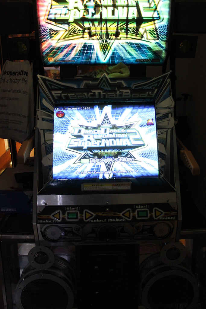
DISCLAIMER: Follow these instructions at your own risk, and be careful. I'm not responsible for your handiwork or lack of soldering skills! And if I've made a mistake (I don't think I have, but those are famous last words), then I'm very sorry but have you heard? The story of the Golden Ninja Warrior?
This thread is a guide to setting up Python 2-based DDR games (SuperNOVA, SuperNOVA 2) on a classic DDR doubles cabinet. Note: you can't get it working on anything except for a legit DDR doubles cab. Comments, corrections and questions are encouraged. If you want to redistribute it elsewhere for whatever reason, do iiiiit.
Before anyone asks, I am not aware of any pirated or bootlegged arcade versions of SuperNOVA or SuperNOVA 2 - I imported my motherboard (and marquee and control panel) from Yahoo Auctions Japan just under a year ago (when all the JP arcades upgraded to DDR X). It's legit (albeit Japanese, not European so I wouldn't be able to put it out on location. It never officially came out in Europe anyway due to the lovely RoHS regulations).
Big shout out and thanks to my main man Zash (for acting as middleman in my quest to get an Ext I/O, and for various conversations over email and PM, for testing that the MC_PWR connection isn't needed, and for actually putting all this into practice by getting his SN2 up-and-running first [and posting pics]). Also thanks to zorahk for clarifying info about the white security plug.
Some of the images are clickable and will take you to my flickr account, where you can get biiiiiig resolution versions. Some are not. The full set is here:
http://www.flickr.com/photos/chi-ryu/ta ... a2upgrade/"
Basic Overview:
You need the following items:
1) Python 2 unit (A.K.A. PS2-in-a-box) with DDR installed and a BLACK security plug[1].
2) Extended I/O unit (EXTIO).
3) Cabling to convert the lights and other I/O plugs into the correct format (see section III), and to provide power to the Python 2 and Ext I/O units.
4) A 100VAC power source - most likely you already have this inside your cabinet[2] (every Japanese and Asian cab I've seen has a 110/120V internal power source off the transformer, but I make no guarantees that every cab in existence does). In particular, I have no idea about EU-distributed Dancing Stage/EuroMIX/EM2 cabinets.
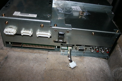
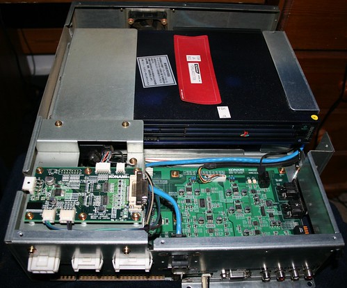
I) Python 2 unit:
The Python 2 unit is the main part for SuperNOVA and SuperNOVA 2.
Lol, it's literally a PS2-in-a-box:
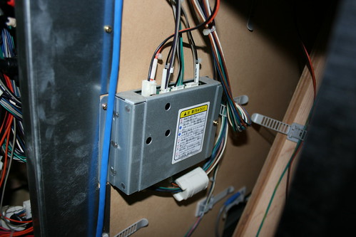
II) Extended I/O unit:
Konami Part number: GKE33-PWB
This converts the lights and pad I/O into the serial format needed for Python 2-based DDR. Without this, the game will throw an I/O error and refuse to boot into game mode (have fun with the service menu if you like, though). Hardware-wise, it looks to be quite simplistic (2 ICs and a bunch of other smaller components), so it's probably possible to reverse engineer it quite easily if someone has the time.
SOURCING THE EXT I/O UNIT
Sadly, the only way to get this at the moment is through Konami's distributors (Betson in the US, Electrocoin in EU), and it's not cheap. The list price in the US is $585, and in the UK/EU it is £659+VAT.
Betson have proved to be a bit flaky with regards to communications - they've outright refused to sell to someone in the US in the past on the grounds that he didn't have a valid US serial number (since he was using a Japanese SuperNOVA 2 main board), and it took me 8 months (and several unanswered emails) to finally get in touch with someone at Betson who actually was competent at his job and replied to emails!
III) Cabling:
There's a bunch of cables required to get this all up and running. The official Konami part numbers are:
[*]GKFDHUA00012 - Neon -> Ext-I/O PCB
[*]GKFDHUA00010 - 1P Lamp -> Ext-I/O PCB
[*]GKFDHUA00011 - 2P Lamp -> Ext-I/O PCB
[*]GKFDHUA00014 - 12V power
[*]GKFDHUA00003 - SCI -> Ext-I/O PCB)
[*]GKFDHUA00013 - Ext-I/O in -> Ext-I/O PCB
[*]GKFDHUA00004 - Lamp PCB -> Python 2 motherboard
...Unless you like soldering cables yourself, you might also like to get a quote for a replacement SN JAMMA loom and these two power cables:
[*] GKFDHUA00007 - JAMMA Loom
[*] GKFDHUA00005 - MC_PWR and 12V power cables
...And if you want to be a completist:
[*] GKFDHUA00061 and GKFDHUA00062 - 120V-100V Transformer and cable
My local distributor wanted GBP£395+taxes for these, so I made my own.
MAKING YOUR OWN CABLES
If you are rolling your own, you'll need to make the following cables:
1) EXTIO power (12V) [Connector: VHR-3N to your DC power supply]
2) Python 2 power (100V) [Connector: VLP-03V, other end to your AC power supply]
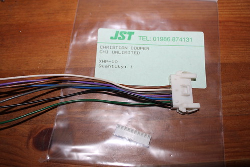
3) 1P lights -> EXTIO [Connectors: XMR-10V to XHP-10]
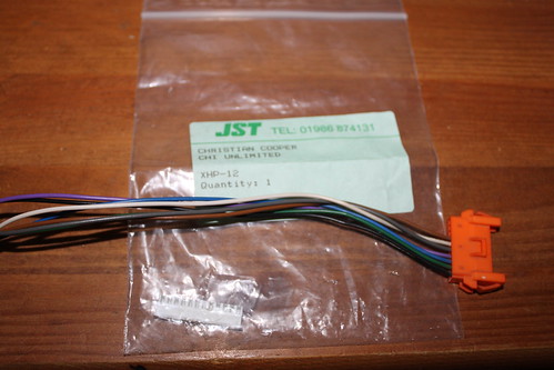
4) 2P lights -> EXTIO [Connectors: XMR-10V to XHP-12]
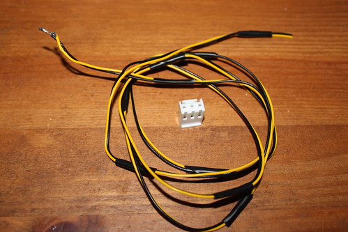
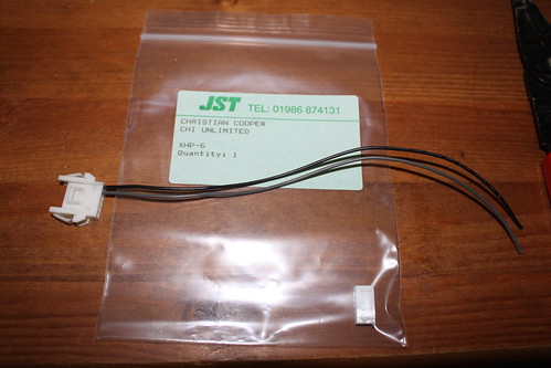
5) Bass Neon -> EXTIO [Connectors: XMR-06V to XHP-6]
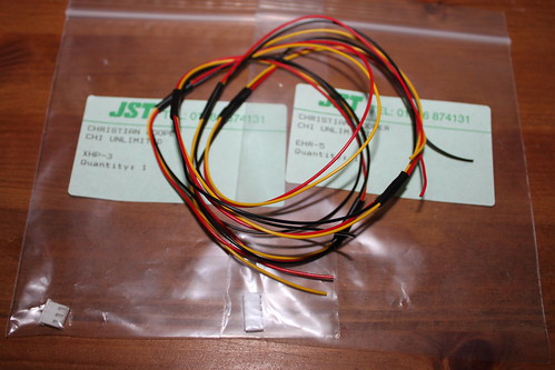
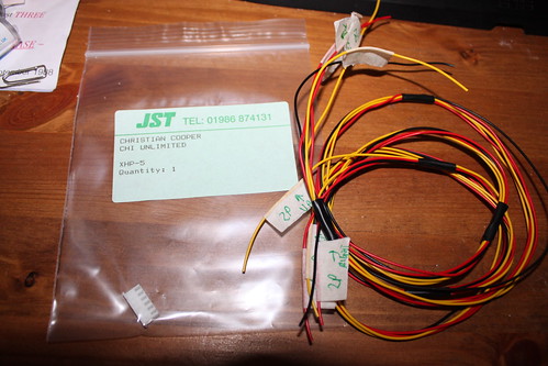
6) Python 2 -> EXTIO [Connectors: EHR-5 to XHP-3]
7) EXTIO -> Jamma loom [Connector: XHP-5, other end soldered onto the JAMMA loom]
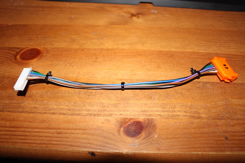
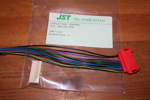
8) Cab lights -> Python 2 [Connectors: XMR-10V to XMP-11V]
9) (OPTIONAL and not needed) Python 2 MC_PWR (5V) [Connector: VHR-4N, other end to your DC power supply]
You'll need the following JST edge connectors:
3 x XMR-10V : Socket for 1P,2P and cab lights from cabinet (I scavenged these from a broken System 573 to save effort)
1 x XMR-06V : Socket for Neon from cabinet (I scavenged these from a broken System 573 to save effort)
1 x VHR-3N : +12V Power for Ext I/O
1 x XHP-3 : Ext I/O to P2 COM1, Ext I/O end
1 x XHP-5 : From JAMMA to Ext I/O
1 x XHP-6 : Neon connector to Ext I/O
1 x XHP-10 : Ext I/O 1P Lights
1 x XHP-12 : Ext I/O 2P Lights
1 x EHR-5 : Ext I/O to P2 COM1, Python 2 end
1 x XMP-11V : To Python 2 (Lamp)
1 x VLP-03V : Python 2 100V power
1 x VHR-4N : MC_PWR +5V (NOT NEEDED, BUT ON THE SCHEMATICS)
You'll need a bunch of pins for these connectors, too:
3 x SEH-001T-P0.6 : EHR contacts
23 x SXA-001T-P0.6: XMR contacts
8 x SXM-001T-P0.6 : XMP contacts
24 x SXH-001T-P0.6 : XHP contacts
4 x SVH-21T-P1.1 : VHR contacts
2 x SVF-42T-P2.0 : VLP contacts
The XMR-connectors I scavenged off a broken System 573 board to save time and effort - they are simply the 4 lights sockets on a 573 motherboard, and can be entirely detatched from the Analogue or Digital I/O board, and then popped out from the face plate.
1) EXTIO power:
Trivial: Pin 1 goes to a +12V source (e.g. JAMMA pin 6 or from your cab's DC power supply), and pin 2 to ground (e.g. JAMMA pin 1)
2) Python 2 power:
Wire pin 1 and pin 2 into an AC 100V supply. The Python 2 unit does not use or require an earth wire. From a functional point of view, it doesn't matter which way round you do this (strictly speaking pin 1 should be AC neutral and pin 2 AC live/hot, but since it's a PS2 in a plastic case inside a sealed unit, it shouldn't be a safety issue if you get it the wrong way round, though as a general principal you should get this the right way round on mains AC stuff).
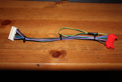
3) 1P lights -> EXTIO
4) 2P lights -> EXTIO
5) Bass Neon -> EXTIO
These are all straight pin-to-pin wirings. The 1P connector (white) goes to the 10-pin XHP housing, the 2P connector (orange) goes to the 12-pin one. The bass neon is the 6-pin white connector.
When finished they'll look like this (2P only shown):
6) Python 2 -> EXTIO [Connectors: EHR-5 to XHP-3]
This is a serial data crossover cable. If you get this wrong, SuperNOVA will give an error when booting and drop out into the operator menu.
Wiring:
EHR pin 1 to XHP pin 2
EHR pin 2 to XHP pin 1
EHR pin 5 to XHP pin 3
7) EXTIO -> Jamma loom [Connector: XHP-5, other end soldered onto the JAMMA loom]
Wiring:
Pin 1 soldered onto JAMMA 1P UP (pin 18)
Pin 2 soldered onto JAMMA 1P RIGHT (pin 21)
Pin 3 soldered onto JAMMA 2P UP (pin V)
Pin 4 soldered onto JAMMA 2P RIGHT (pin Y)
Pin 5 soldered onto JAMMA ground (e.g. pin 1)
8) Cab lights -> Python 2 [Connectors: XMR-10V to XMP-11V]
Wiring:
XMR Pin 1 to XMP pins 1 and 6 (grounds)
XMR Pin 4 to XMP pin 2
XMR Pin 5 to XMP pin 3
XMR Pin 6 to XMP pin 7
XMR Pin 7 to XMP pin 8
XMR Pin 8 to XMP pin 9
XMR Pin 9 to XMP pin 10
XMR Pin 10 (earth) not required.
When finished it'll look like this:
9) (OPTIONAL and not needed) Python 2 MC_PWR (5V)
As with cable #1, this is trivial. Pin 1 goes to +5V (e.g. JAMMA pin 3 or from your cab's DC power supply), pin 2 to ground (e.g. JAMMA pin 1). It's also not needed - this is used to power the memory card sub-board on the Python 2, which ultimately was not used in SuperNOVA/SN2.
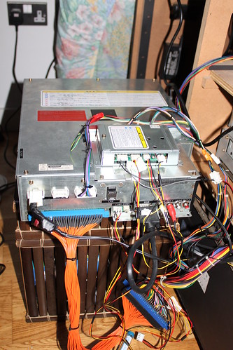
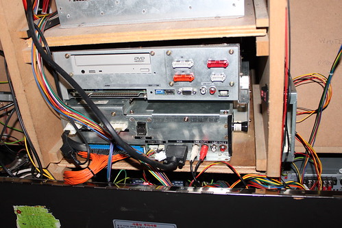
When it's all finished and cabled up, it sohuld look a bit like this:
On a Korean cab, there's space to store the old System 573 unit on top of the Python 2 unit for quick changes (you might not be able to do this with a Japanese cab as they store the units vertically instead of horizontally):
Appendix A) Schematics:
Annotated SuperNOVA schematics (showing the differences from ye olde cabs) can be found here:
http://www.flickr.com/photos/chi-ryu/tags/snvsoldddr/"
Appendix B) JAMMA Pinouts
A breakdown of the JAMMA pinouts can be found e.g. here: http://www.coin.demon.co.uk/jamma.htm"
[1] Often these units are seen with two security plugs (one black one white) - you only need the black one. The white one is a hardware identifier plug - used to identify the machine on e-Amusement, amongst other things.
[2] Usually there is an internal 120VAC source for cabinets used outside of Japan, but it doesn't really make a difference in practical terms. If you want to be a completest, get a 120V-100V stepdown for the Python 2 (you can find them in airports in Japan, or mail ordered for silly money), but I didn't bother. If you are happy enough to run a Japanese Playstation 2 from US mains/120V stepdown, this is literally no different.
How-to: Install Python 2 DDR games into old DDR cabs
-
Chi

- Fire Extinguisher
- Posts: 904
- Joined: August 18th, 2008, 12:55 am
- Location: Croydon, UK
- Initials: CHI
How-to: Install Python 2 DDR games into old DDR cabs
Not sure if this should live here or in Cabinet Q&A, but I figured I'd post a copy of this here for archiving and info (not that it's likely anyone will want to do what I've done here  ). It was written by me for a DDR forum.
"TO THE untrained eye Christian Cooper might have been stamping out a small fire " - The Times, 7th Feb, 2004
-
Devil Soundwave

- Doesn't go to eleven
- Posts: 4713
- Joined: January 7th, 2009, 11:56 pm
- Location: Wetherby, Yorkshire
- eBay: DevilSoundwave
Re: How-to: Install Python 2 DDR games into old DDR cabs
Put it in the wiki man!
-
Chi
- Fire Extinguisher
- Posts: 904
- Joined: August 18th, 2008, 12:55 am
- Location: Croydon, UK
- Initials: CHI
Re: How-to: Install Python 2 DDR games into old DDR cabs
Ok, at some point, but that'll involve converting the bbcode inside it to wikicode - it was much easier to copy and paste straight outDevil Soundwave wrote:Put it in the wiki man!
"TO THE untrained eye Christian Cooper might have been stamping out a small fire " - The Times, 7th Feb, 2004
-
serantes
- Please Continue...
- Posts: 174
- Joined: September 2nd, 2008, 6:27 pm
- Location:
Re: How-to: Install Python 2 DDR games into old DDR cabs
could you post the source url for this post ?
i would like to see if anyone asked where to get the jst connectors there, else i will do it

i would like to see if anyone asked where to get the jst connectors there, else i will do it
-
Chi
- Fire Extinguisher
- Posts: 904
- Joined: August 18th, 2008, 12:55 am
- Location: Croydon, UK
- Initials: CHI
Re: How-to: Install Python 2 DDR games into old DDR cabs
One's on a private forum, the other is here:serantes wrote:could you post the source url for this post ?
i would like to see if anyone asked where to get the jst connectors there, else i will do it
http://zenius-i-vanisher.com/v5.2/viewt ... eadid=2822"
I can't help you with sourcing the JST connectors, I'm afraid.
"TO THE untrained eye Christian Cooper might have been stamping out a small fire " - The Times, 7th Feb, 2004
-
serantes
- Please Continue...
- Posts: 174
- Joined: September 2nd, 2008, 6:27 pm
- Location:
Re: How-to: Install Python 2 DDR games into old DDR cabs
where did you get the connectors from so ?Chi wrote:One's on a private forum, the other is here:serantes wrote:could you post the source url for this post ?
i would like to see if anyone asked where to get the jst connectors there, else i will do it
http://zenius-i-vanisher.com/v5.2/viewt ... eadid=2822"
I can't help you with sourcing the JST connectors, I'm afraid.
and could you post the url or name of this private forum ?
-
The Enigmatic Form

- Please Continue...
- Posts: 393
- Joined: August 20th, 2008, 5:31 pm
- Location: Hannover, Germany
Re: How-to: Install Python 2 DDR games into old DDR cabs
The photo with the PS2 is one of the greatest things I've ever seen. 
-
dieKatze88
- Please Continue...
- Posts: 485
- Joined: July 21st, 2009, 6:43 am
- Location: Madison, NJ
Re: How-to: Install Python 2 DDR games into old DDR cabs
I was in fact one of the first persons to take such a photo when I took pictures of TGA's SuperNOVA kit back in 2006.The Enigmatic Form wrote:The photo with the PS2 is one of the greatest things I've ever seen.
Speaking of which, I do *HAVE* TGA's old Serial Number. I guess on the grounds of that if betson ever gives you **** again, call me and I'll order the **** part.
I stream myself playing Otomedius when I get bored
http://www.ustream.tv/channel/otomedius" onclick="window.open(this.href);return false;
http://www.ustream.tv/channel/otomedius" onclick="window.open(this.href);return false;
-
Chi
- Fire Extinguisher
- Posts: 904
- Joined: August 18th, 2008, 12:55 am
- Location: Croydon, UK
- Initials: CHI
Re: How-to: Install Python 2 DDR games into old DDR cabs
Yeah, I love the whole laziness of "let's just stick a PS2 in and be done with it" - a tactic that backfired on Konami a year later when RoHS came into force in Europe and it became illegal to import anything containing phat PS2s as they are not RoHS compliant... thus meaning Dancing Stage SuperNOVA 2 could not be released.
Cheers dude - Betson didn't give me any **** (I don't think their International department cares about anything other than making money), it was Zash who got told to bugger off because he was trying to get parts for a JP SuperNOVA 2 in the US.dieKatze88 wrote:Speaking of which, I do *HAVE* TGA's old Serial Number. I guess on the grounds of that if betson ever gives you **** again, call me and I'll order the **** part.
"TO THE untrained eye Christian Cooper might have been stamping out a small fire " - The Times, 7th Feb, 2004
-
andygeezer

- Blue Skies Ahead
- Posts: 2427
- Joined: August 24th, 2008, 12:25 pm
- Location: Cambridge, UK
- Initials: AGS
Re: How-to: Install Python 2 DDR games into old DDR cabs
Slightly OT, but the price on DDR machines has dropped right out, I've known companies to scrap them now.. they seem to be worthless.
Say hello to my little friend...

-
Chi
- Fire Extinguisher
- Posts: 904
- Joined: August 18th, 2008, 12:55 am
- Location: Croydon, UK
- Initials: CHI
Re: How-to: Install Python 2 DDR games into old DDR cabs
Yup, I've seen old ones (Asian/Korean 3rdMIXes) sell for less than £700 recently - there's dozens of these units around the country in various storages, and no-one would want to operate one.andygeezer wrote:Slightly OT, but the price on DDR machines has dropped right out, I've known companies to scrap them now.. they seem to be worthless.
To be honest, the parts inside are worth more than the cabinets (the System 573 Digital still goes for £200-250, and the Stage I/O boards are still worth money as spares, given that Konami charge several hundred pounds for replacements). The newer SuperNOVA cabs are worth a bit more, though (though I doubt anyone would get more than about 2 large for one of those, even). The stages themselves could be worth a bit of cash if handled properly (there's still non-trivial numbers of fanboys that would pay a few hundred quid to have one of those if it were cleaned up a bit and adapted for home use - especially if it were just half a stage).
Strange to think that just 15 months ago even these rustbuckets were going for between £2,000-3,000... and muggins here bought just a few weeks before the big price crash(tm).
"TO THE untrained eye Christian Cooper might have been stamping out a small fire " - The Times, 7th Feb, 2004
-
Parris
- The ¥100 Ashtray
- Posts: 1008
- Joined: August 18th, 2008, 8:28 pm
- Location:
Re: How-to: Install Python 2 DDR games into old DDR cabs
Being a bit of a PS2 fan it's not the first time I've seen Sony PS1 or PS2 components lurking inside a cabinet, but the Python2 really does take this to an entirely new level of "lazy". A complete Midnight Blue PS2 stuck inside the cab lol. The Midnight Blue was a Japanese / Asian only release and it was the only official PS2 sold with the Network Adapter and 40Gb HDD ready to go. I hope you don't mind (I know you say about redistributing it elsewhere is fine), but I am going to link to another site where I think some of the Sony users will be interested in this.
The original retail console is here: http://www.play-asia.com/paOS-13-71-o-49-en-70-2fb.html"
Nice job - thanks for posting the thread and if you ever get a knackered Python2, please let me know as I'd love to have a look at it.
Also out of interest does the DDR unit employ the optical out from the PS2 as it's not disabled on the System units (I checked). *Edit, just noticed the RCA outputs, so that'll be a no then!
-
Chi
- Fire Extinguisher
- Posts: 904
- Joined: August 18th, 2008, 12:55 am
- Location: Croydon, UK
- Initials: CHI
Re: How-to: Install Python 2 DDR games into old DDR cabs
Yes, audio is through the optical out.Parris wrote:Also out of interest does the DDR unit employ the optical out from the PS2 as it's not disabled on the System units (I checked). *Edit, just noticed the RCA outputs, so that'll be a no then!
"TO THE untrained eye Christian Cooper might have been stamping out a small fire " - The Times, 7th Feb, 2004
-
dieKatze88
- Please Continue...
- Posts: 485
- Joined: July 21st, 2009, 6:43 am
- Location: Madison, NJ
Re: How-to: Install Python 2 DDR games into old DDR cabs
Well the big price crash hurt the prices of machines, but Honestly I don't think you guys are right about not wanting to operate them. They are *STILL* the biggest earners in American arcades. one local arcade pulls 3 to 4k a week out of theirs. and they HAVE a Guitar Hero Arcade that doesn't do well either. Go figure.Chi wrote:Yup, I've seen old ones (Asian/Korean 3rdMIXes) sell for less than £700 recently - there's dozens of these units around the country in various storages, and no-one would want to operate one.andygeezer wrote:Slightly OT, but the price on DDR machines has dropped right out, I've known companies to scrap them now.. they seem to be worthless.
To be honest, the parts inside are worth more than the cabinets (the System 573 Digital still goes for £200-250, and the Stage I/O boards are still worth money as spares, given that Konami charge several hundred pounds for replacements). The newer SuperNOVA cabs are worth a bit more, though (though I doubt anyone would get more than about 2 large for one of those, even). The stages themselves could be worth a bit of cash if handled properly (there's still non-trivial numbers of fanboys that would pay a few hundred quid to have one of those if it were cleaned up a bit and adapted for home use - especially if it were just half a stage).
Strange to think that just 15 months ago even these rustbuckets were going for between £2,000-3,000... and muggins here bought just a few weeks before the big price crash(tm).
We STILL have arcades with 2 or 3 of them in popular areas, ****, before TGA closed they had FOUR DDR machines (one of each kind! One American, One Japanese, One SuperNOVA, and One Korean) and a Pump It Up, and every time I was in the place there was someone on all of the machines.
Man, I'll tell you one thing though, cleaning these things is a *BITCH*. At least its not as bad as cleaning the DDR X machines (Read: You have to remove the entire top cover of the pad to make repairs on any one panel, as opposed to current machines where you can remove individual panels) For anyone who has ever done this, they know exactly how bad it is. I showed up to Bowlmanifest 07 at TGA 2 days early to spend an entire day cleaning the DDR SuperNOVA cab's pads for the 1000 dollar tourney that we held that summer. It took me half the day to get the pad clean, and another day and a half of testing by the customers to get the thing to a fully playable state. So I can offer advice and repair information on these things if anyone needs it, but I'll cover the most important one right here: DO NOT FORGET TO PUT *ALL THREE* OF THE SCREWS IN THE L BRACKETS! WITHOUT ALL THREE YOUR L BRACKET WILL PROBABLY STICK, AND YOUR PANEL WILL GHOST OR STAY ACTIVATED!
Still, I would operate one if I was running an arcade, its still a cash cow. Even an older version. X2 is supposed to be "The ****" in terms of getting a new generation of players on the machines though. I'm not exactly sure how well that will go though.
I stream myself playing Otomedius when I get bored
http://www.ustream.tv/channel/otomedius" onclick="window.open(this.href);return false;
http://www.ustream.tv/channel/otomedius" onclick="window.open(this.href);return false;
-
Chi
- Fire Extinguisher
- Posts: 904
- Joined: August 18th, 2008, 12:55 am
- Location: Croydon, UK
- Initials: CHI
Re: How-to: Install Python 2 DDR games into old DDR cabs
Update: I was wondering how to switch the Python 2 into 31kHz mode, and Zash pointed the answer out to me; it was staring me in the face in the schematics all along! I've updated the guide accordingly with the following text:
There's also a glut of really old Asian 3rdMIXes (they are actually exactly the same hardware as 3rdMIX ver.KOREA 2 - a simple disk swap of original disks will reinstall), but they are in such bad shape they'd need a bunch of work before they are fit to go in an arcade, and there are so many beat-up machines on location here which will only get one credit from anyone (casual or fan) before they give up from pad misses (not to mention almost dead monitors).
Also, from what I hear, TGA had an awesome community - most arcades over here are casual affairs linked to bowling alleys, etc.
dieKatze88: I've not spoken to ops that have it, but on appearances DDR X doesn't appear to be doing that well this side of the pond - the US/EU cabs have had a lot of teething trouble and require quite a bit of maintenance. They still have non-trivial lag problems too (as does Guitar Hero AC). I feel your pain with maintaining these cabs in full working order - it's a nontrivial amount of work stripping down the panels and cleaning everything up. I've foam-modded my pads to compensate for the fact that the sensors are quite old - if my cab was on location, this would need re-doing every 6-9 months.FINAL NOTE: By default, Python 2 outputs 15kHz (nominally this is at 0.7Vp-p through the D-sub connector, and 3.3Vp-p (arcade monitor voltage) on the JAMMA. To switch this to 31kHz (if you have a suitable monitor), simply bridge together JAMMA pins S and M (thanks to Zash for pointing this out!).
There's also a glut of really old Asian 3rdMIXes (they are actually exactly the same hardware as 3rdMIX ver.KOREA 2 - a simple disk swap of original disks will reinstall), but they are in such bad shape they'd need a bunch of work before they are fit to go in an arcade, and there are so many beat-up machines on location here which will only get one credit from anyone (casual or fan) before they give up from pad misses (not to mention almost dead monitors).
Also, from what I hear, TGA had an awesome community - most arcades over here are casual affairs linked to bowling alleys, etc.
"TO THE untrained eye Christian Cooper might have been stamping out a small fire " - The Times, 7th Feb, 2004
-
dieKatze88
- Please Continue...
- Posts: 485
- Joined: July 21st, 2009, 6:43 am
- Location: Madison, NJ
Re: How-to: Install Python 2 DDR games into old DDR cabs
Well its for all the reasons you mentioned. DDR X isn't doing well at all, but maintenance is a **** NIGHTMARE, tearing down a regular DDR pad was bad enough, but when you have ONE LARGE PIECE OF STEEL THAT YOU HAD BETTER NOT BEND to take off instead of 10 little ones, it becomes even MORE problematic. There's one DDR X in New Jersey where I am, and I haven't even bothered. its on the boardwalk. those pads are going to be FULL of sand and you're DAMN sure they're not cleaning that out.Chi wrote:Update: I was wondering how to switch the Python 2 into 31kHz mode, and Zash pointed the answer out to me; it was staring me in the face in the schematics all along! I've updated the guide accordingly with the following text:
dieKatze88: I've not spoken to ops that have it, but on appearances DDR X doesn't appear to be doing that well this side of the pond - the US/EU cabs have had a lot of teething trouble and require quite a bit of maintenance. They still have non-trivial lag problems too (as does Guitar Hero AC). I feel your pain with maintaining these cabs in full working order - it's a nontrivial amount of work stripping down the panels and cleaning everything up. I've foam-modded my pads to compensate for the fact that the sensors are quite old - if my cab was on location, this would need re-doing every 6-9 months.FINAL NOTE: By default, Python 2 outputs 15kHz (nominally this is at 0.7Vp-p through the D-sub connector, and 3.3Vp-p (arcade monitor voltage) on the JAMMA. To switch this to 31kHz (if you have a suitable monitor), simply bridge together JAMMA pins S and M (thanks to Zash for pointing this out!).
There's also a glut of really old Asian 3rdMIXes (they are actually exactly the same hardware as 3rdMIX ver.KOREA 2 - a simple disk swap of original disks will reinstall), but they are in such bad shape they'd need a bunch of work before they are fit to go in an arcade, and there are so many beat-up machines on location here which will only get one credit from anyone (casual or fan) before they give up from pad misses (not to mention almost dead monitors).
Also, from what I hear, TGA had an awesome community - most arcades over here are casual affairs linked to bowling alleys, etc.
I hear superior rumors that Konami of Japan has stepped in and said "No. This ends now" about the pad issues on DDR X, and is going to fix it. Don't quote me. As for the timing issues, It'll be like SuperNOVA 1, wait until the patch. Get your DDR X's Ethernet connected because Konami DOES roll out patches that way. We got some that way at TGA before the patch disc.
The older DDR machines are actually rather nice to maintain. The older these cabs are, the better they are, and even if they're in rickety **** shape, if you spend a weekend cleaning, painting, and getting the machine up nice, the machine will be in factory state, no ****. The pad is a huge problem, but the whole thing is machine washable, so you take the pad apart, take the top 10 pieces of steel, and the top 8 pieces of plastic (READ: KONAMI OFFICIAL ONLY CONFIRMED TO BE MACHINE WASHABLE!) and all of the corner braces and throw them in the dishwasher for an hour. Two rinse cycles. Spend that hour, cleaning the bottom. Done. Replace sensors if really bad, use penny mod if high accuracy required (Read: Place 2 US Penny sized coins underneath the Lbracket on top of the sensor. 3 year olds will register your panels EVERY SINGLE TIME). Your panels should be clean now, go get them, put them back. Pad workable forever at home, 9 months on location. guaranteed.
Save the series! fix your machines. I volunteer to repair these machines at my local arcades if they're bad enough. I used to maintain a 5th mix near my house in a bike shop in town. Great machine. NOBODY ever complained about those pads because I fixed it right the FIRST time.
Man if you want to own a DDR machine (and don't already) those 3rds are a STEAL. They've got 573 digitals (and thus can run anything worth running from the 573 era) are easy to restore to full working order (**** I'll do it for you. Pay me and buy the parts) and are usually **** cheap as hell. Also, thanks to soft 15khz, I can have them running Stepmania in about 90 minutes from no computer to fitted with XP and Ready to go. The Tubes on those things are usually pretty good, but burned. Replace if you care, but the honest situation about DDR tubes is, they all burn in the EXACT SAME SPOT and you won't notice it while playing.
TGA was **** awesome. I still talk to a good number of the friends I made there, and Plan on going up to MA for the next Community meetup as soon as I have cash (But I have to buy a new laptop first. Plz donate to my "Not having a laptop but needing one for school" cause!) and the time. Its an honest shame that more arcades like TGA don't exist, because if they did we wouldn't need to buy our own cabs, or need mame all the time. Really. It would just be a perfect world with unicorns and rainbows, no war, a stable economy where every single person has a high paying job, and free beer. Yes. That **** good.
I stream myself playing Otomedius when I get bored
http://www.ustream.tv/channel/otomedius" onclick="window.open(this.href);return false;
http://www.ustream.tv/channel/otomedius" onclick="window.open(this.href);return false;
-
Chi
- Fire Extinguisher
- Posts: 904
- Joined: August 18th, 2008, 12:55 am
- Location: Croydon, UK
- Initials: CHI
Re: How-to: Install Python 2 DDR games into old DDR cabs
Aside from a blown CCFL controller in one of the pads (which I must get around to replacing), my personal machine (which was a dustbin 3rdMIX Asian 14 months ago, and I'm sure was operated in a swampdieKatze88 wrote:Save the series! fix your machines. I volunteer to repair these machines at my local arcades if they're bad enough. I used to maintain a 5th mix near my house in a bike shop in town. Great machine. NOBODY ever complained about those pads because I fixed it right the FIRST time.
I've known 5-6 UK fans who have bought their own cab in the past 12 months (since the price dropped so much), at least that's some cabs saved from the bin. Problem is that the Asian/Korean cabs are dustbins compared to the JP ones (and it's obvious in e.g. the quality of the CRT used - Samsung tubes with rubbish chassis).
Konami of Japan have jack **** to do with the production of the NA/EU cabs aside from producing the software (and shouting at Konami of Europe and USA regularly) - they were (predominately) Raw Thrills built and Betson/Electrocoin distributed. You should see the mess of wiring inside the cab (compared to the JP SuperNOVA cab, for instance - I've not seen inside a JP DDR X). I'm not sure what KoJ will - or can - do apart from shout, really. Hopefully something will be done, though.
The lag issues are only issues with the inferior build-quality US/EU cabs, not really with the JP ones (thus I suspect cheap and laggy LCDs). Konami of Europe (and Konami USA) have tried their best to rectify the problems in hindsight - and have done a good job considering what they had to work with (as in: I've used a DDR X with hyper sensitive pads after Konami modding) - but the cabs aren't in the same league in build quality to the classic cabs. Hell, they aren't even playing the same sport.
We've not had an arcade like TGA for a good decade now. Namco Great Windmill Street in London was awesome back in the day - was a sad day when they sold up. Casino in Goodge Street, London has potential (good community base, good games - often lent by the community), but has crap cabs.
"TO THE untrained eye Christian Cooper might have been stamping out a small fire " - The Times, 7th Feb, 2004
-
dieKatze88
- Please Continue...
- Posts: 485
- Joined: July 21st, 2009, 6:43 am
- Location: Madison, NJ
Re: How-to: Install Python 2 DDR games into old DDR cabs
Ahhh, see thats where this is unique. KOJ is apparently actually stepping in and sending people to take over some other people's jobs, its so bad. Historically, Konami hasn't ever given half a **** about Europe (Look at the history of how things are released. You guys have gotten the shaft since 1985.) so I'm not sure how far that will fly for you, but considering their worldwide strategy to DDR now, you'll probably win this time. I hear whispers of an entire pad replacement kit that removes the pad from being linked to the machine and causes many people at raw thrills to lose their jobs.Chi wrote:Aside from a blown CCFL controller in one of the pads (which I must get around to replacing), my personal machine (which was a dustbin 3rdMIX Asian 14 months ago, and I'm sure was operated in a swampdieKatze88 wrote:Save the series! fix your machines. I volunteer to repair these machines at my local arcades if they're bad enough. I used to maintain a 5th mix near my house in a bike shop in town. Great machine. NOBODY ever complained about those pads because I fixed it right the FIRST time.
I've known 5-6 UK fans who have bought their own cab in the past 12 months (since the price dropped so much), at least that's some cabs saved from the bin. Problem is that the Asian/Korean cabs are dustbins compared to the JP ones (and it's obvious in e.g. the quality of the CRT used - Samsung tubes with rubbish chassis).
Konami of Japan have jack **** to do with the production of the NA/EU cabs aside from producing the software (and shouting at Konami of Europe and USA regularly) - they were (predominately) Raw Thrills built and Betson/Electrocoin distributed. You should see the mess of wiring inside the cab (compared to the JP SuperNOVA cab, for instance - I've not seen inside a JP DDR X). I'm not sure what KoJ will - or can - do apart from shout, really. Hopefully something will be done, though.
The lag issues are only issues with the inferior build-quality US/EU cabs, not really with the JP ones (thus I suspect cheap and laggy LCDs). Konami of Europe (and Konami USA) have tried their best to rectify the problems in hindsight - and have done a good job considering what they had to work with (as in: I've used a DDR X with hyper sensitive pads after Konami modding) - but the cabs aren't in the same league in build quality to the classic cabs. Hell, they aren't even playing the same sport.
We've not had an arcade like TGA for a good decade now. Namco Great Windmill Street in London was awesome back in the day - was a sad day when they sold up. Casino in Goodge Street, London has potential (good community base, good games - often lent by the community), but has crap cabs.
The LCD Lag issue isn't in the unfixable range, which is what **** me off. I recently produced a DDR game for a capstone, and we were given a 40 inch LCD TV with gigantic lag to present the game with. 20 seconds and I had the game running with full sync.
I think these new cabs have great potential! but only the Cabs. Konami has to get the pads physically disconnected from the machine, and get new software rolled out, and these cabs *WILL* be great. its not a matter of if or when.
That is totally lame. You guys collectively seem to have alot of cabs, you could community arcade it. Just a thought.
I stream myself playing Otomedius when I get bored
http://www.ustream.tv/channel/otomedius" onclick="window.open(this.href);return false;
http://www.ustream.tv/channel/otomedius" onclick="window.open(this.href);return false;
-
Deathbyillusion
- Please Continue...
- Posts: 11
- Joined: November 11th, 2011, 5:08 am
- Location:
Re: How-to: Install Python 2 DDR games into old DDR cabs
Hey guys I need help with my DDR EXTREME ARCADE MACHINE I just bought it is running it using a Playstation 2 and had HDAdvance 2.0 disc in the Playststion 2 which is a game manager to play backups from the manager. The problem I am having is when I turn it on it turns on and starts the Playstation 2 sound and that it loads the game disc but on the screen it shows a blank white screen and at the bottom it says "MULTIGAME" then about 10 seconds later it changes and then says "P2:44" I dont think there is anything wrong with the moniter cause of what it shows and its a clear screen not fuzzy or anything. Also in the back I noticed there is a a yellow t shaped double sided video av cable not plugged into anything and I think thats what needs to be hooked into somewhere. I have posted a thread about this on another forum site with replys and it goes into more details on the problem and pics of whats going on. http://forums.arcade-museum.com/showthr ... on+extreme"
If someone could help me with this cause I cant find anywhere that tells me much and this was the closest place I could find. that would be awesome cause this is driving me crazy!
Thanks
If someone could help me with this cause I cant find anywhere that tells me much and this was the closest place I could find. that would be awesome cause this is driving me crazy!
Thanks
-
Jamtex

- Please Continue...
- Posts: 100
- Joined: May 20th, 2011, 9:10 pm
- Location: Oslo, Norway
Re: How-to: Install Python 2 DDR games into old DDR cabs
More OT, where can one find these cheap and cheerful DDR cabinets? I would like one for an exhibition, I bought a pump it up as it was cheap but the motherboard has died, no one can or wants to fix them and I have tried desperately to find a V3 or V5 motherboard without some joker asking stupid money for them.
A:>