Taito Rastan Repairlog

PCB problems and fixes
Womble
Please Continue...
Posts: 95
Joined: November 19th, 2009, 9:32 am
Location:

Taito Rastan Repairlog

Post by Womble »

Got this one in a large batch of boards recently, looked in very good nick, and the game booted and ran but the graphics were pretty messed up. The screen had crazy colours and vertical lines through everything.

Image

Image

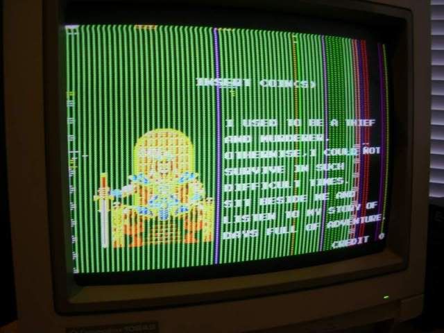
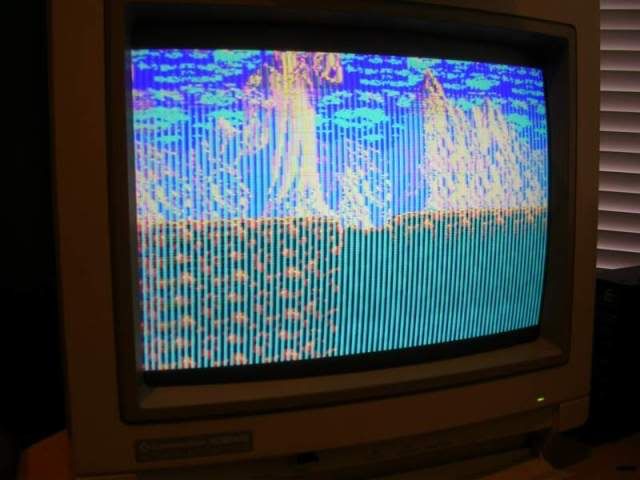
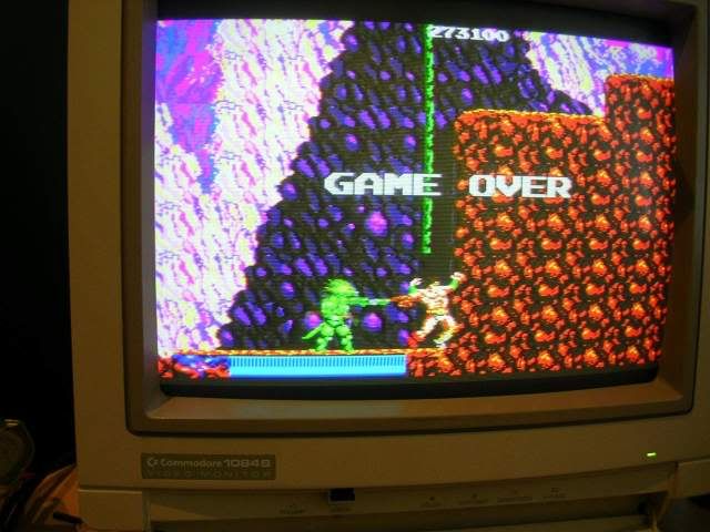
All in game sprites were missing too!

Image

First thing to do is a visual inspection, looking for any damage, the board looked pretty mint, no gouges or scratched tracks, but a cap was missing from the amp section, which someone had labelled with a black arrow in texter...

Image

..and someone had removed and replaced a couple of TMM2018 SRAM chips from a bank of 4, IC2 and IC3 were still soldered on the board, whereas IC4 and IC5 not..

Image

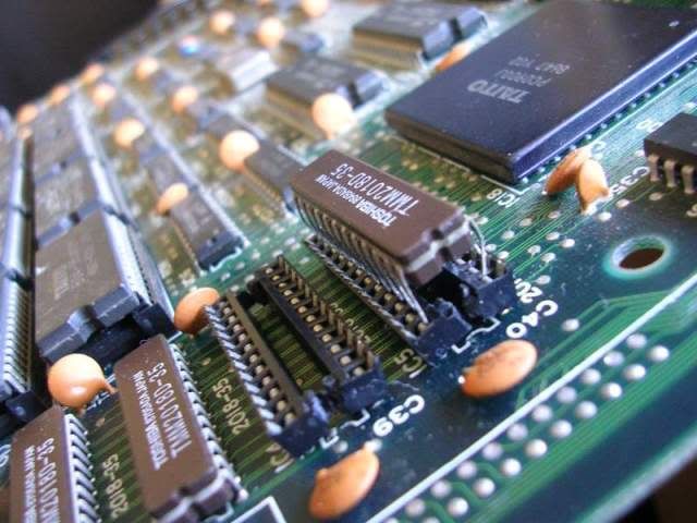
..they had been desolded, and fitted into sockets made out of cut up parts of other sockets. Sadly whoever didn't use a chip to get the spacing right so the halves were wonky and the chip legs had to go down the outside of the contact pad bending the socket fragments and the chip legs at the same time.

Also on removing the two chips from their makeshift sockets it was obvious that one had lost half its ground pin...

Image

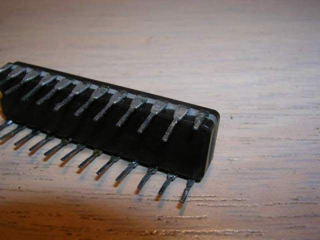
...presumably because 5V and ground pins are often hard to desolder due to the amount of copper attached to them wicking the heat away so quickly the solder never fully melts.

The remains of the leg were just long enough to look like it was a normal leg in the socket, but not long enough to actually make contact.

On removal of the half sockets them more damage was evident...

Image

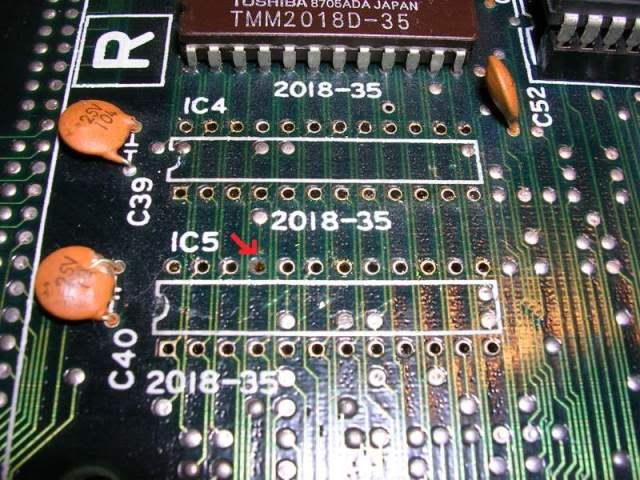
....pin 21 on the lower chip had ripped the plate through hole out of the board, breaking the connection to that pin. The pin is actually the WE (write enable) pin which allows the board to tell the chip to go into write mode, as opposed to read mode, without this pin the CPU can never actually store data in the chip.

A quick buzz round with the continuity beeper confirmed that this was the only borked pad so I fitted a couple of sockets. As there was no plate through hole to solder pin 21 to I fitted a wire link to the nearby via where the original track had run.

Fixing the leg on the 2018 chip was simple too, I trimmed the thin end of the broken leg, put the chip into a machined pin socket and inserted a pin cut from a faulty chip in my bin into the socket hole. One this was lined up properly and pushed into the socket firmly I soldered it to the tag left on the original leg. On removal from the socket it is actually hard to tell its been patched up. As the chip was now usable I could test it with its pair in my EPROM reader and both chips passed the test.

So I put them back on the board..

Image

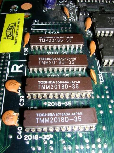
..and powered it up, everything was perfect again, the graphics artifacts were gone and all sprites were back.

Image

Image

Image

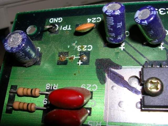
At this stage the game was working fine, the sound was good too, but the missing cap was included in the design for a reason, its there, along with a 0.1uF polyester cap to filter power supply hum on the 12V rail, so it needs to be there.

I tracked down the schematics and confirmed what the missing cap should be, a 1000uF 16V, and I had a spare from a scraped TV board. I removed the remains of the original cap legs, cleaned the black texter arrow off the board with some acetone and fitted the "new" cap in place...

Image

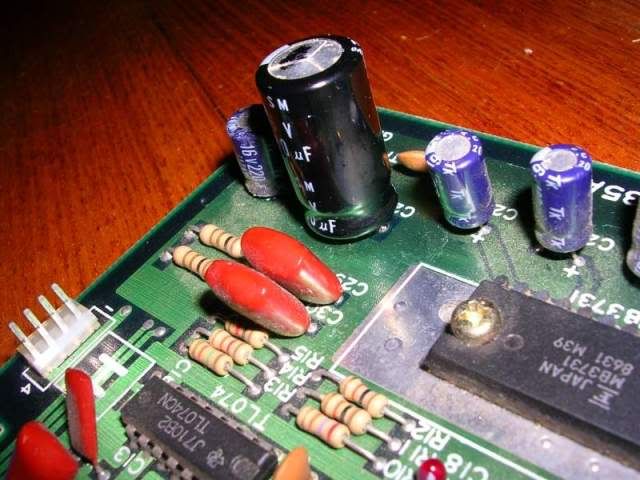
...it looks like the cap is bulging in this photo but its actually perfectly flat, just the flash I think.

The game has been running in my cab for over an hour now without any issues at all. :)

I did originally wonder why those two chips had been replaced as they looked like they were the original chips, as they were almost identical to the other pair in the bank of four. Also as the only fault was the damage done during their replacement it begged the question why they were replaced in the 1st place. But on closer inspection the batch number of the pair differ from the ones still on the board, so the original ones probably were the cause of the fault, the previous repairer just made things worse while tying to replace them and probably just gave up.
User avatar
gargoyle67
The movie topic guy!
Posts: 5083
Joined: August 22nd, 2008, 11:33 am
Location: Clacton-On-Sea init
eBay: gargoyle1967

Re: Taito Rastan Repairlog

Post by gargoyle67 »

As always interesting read Womble, Rastan's a great Conan ripoff game too with prob the best most dramatic music I've heard in a video game 8-)
"Yeah lets all get ponys instead, wait no lol trendy cabs" Err I think you meant Ponies didn't you ?
User avatar
Rossyra
Supermod
Posts: 7902
Joined: February 12th, 2009, 1:24 am
Location: UK

Re: Taito Rastan Repairlog

Post by Rossyra »

Nice job Womble.
Image
User avatar
JAMMArob
Please Continue...
Posts: 184
Joined: November 18th, 2008, 12:50 pm
Location: Texas, USA

Re: Taito Rastan Repairlog

Post by JAMMArob »

I *MUST* get one of those solder vacuums.
Image
User avatar
Devil Soundwave
Doesn't go to eleven
Posts: 4713
Joined: January 7th, 2009, 11:56 pm
Location: Wetherby, Yorkshire
eBay: DevilSoundwave

Re: Taito Rastan Repairlog

Post by Devil Soundwave »

jamma4life wrote:I *MUST* get one of those solder vacuums.
They're really not that great.

In fact, desoldering is just a bitch generally.

Womble - i have a standalone solder vacuum that you use alongside a soldering iron, a self-contained heated solder-vacuum and some desoldering braid; yet I still find 90% of the time I just have to chop off whatever component I need to remove.

Do you have any tips on desoldering specifically?
Womble
Please Continue...
Posts: 95
Joined: November 19th, 2009, 9:32 am
Location:

Re: Taito Rastan Repairlog

Post by Womble »

Devil Soundwave wrote:
jamma4life wrote:I *MUST* get one of those solder vacuums.
They're really not that great.

In fact, desoldering is just a bitch generally.

Womble - i have a standalone solder vacuum that you use alongside a soldering iron, a self-contained heated solder-vacuum and some desoldering braid; yet I still find 90% of the time I just have to chop off whatever component I need to remove.

Do you have any tips on desoldering specifically?
Judging by the troubles you are having I would put money on you trying to desolder a joint without adding new solder to it first...this is almost impossible.

I wrote the following guide on another site a long while ago, so have updated it here...

When I 1st got the desolder station I was not overly impressed, but after a month or two with it I can honestly say its utterly awesome, probably is the 3rd most used tool in my armoury after scope and soldering iron. It takes a little practice to get good at it but once you have it nailed you can get components to litterally fall off the board with no damage to the chip or to the board itself. To practise I went through my scrap drawer recovering CPUs and RAM chips - got a dozen or so 68000s, 768 pins on the 68000s alone.

I have a couple of tips for its use tho.

1) Use pliers to straighten any bent pins on the chip before you try to desolder, dont try to use the desolder nozzle to do the straightenning, it doesnt work well and you end up with a half cleared pin which wastes more time than fixing the pins first.

2) Re-tin the joint you are about to clear, this is utterly essential, especially with very old low lying joints. With a soldering iron get a blob of solder on to the joint, doesnt have to be neat, but heat it with the soldering iron until you can see the new solder mix with the old. This achieves two things, firstly it gets some flux into the joint, without flux the old solder is going nowhere, and you will roast the board trying to get it out. Secondly it adds metal which gives more surface area to transmit the heat through, sometimes a bigger blob is better than a small one.

3) Secondly you need to be aware whats around the solder joint you are trying to remove, any tracks nearby are at risk as the desolder nozzle is bloody hot, you need to waggle the pin when you have the solder hot as you hit the vacuum pump button. Try and do your waggling into blank space rather than over any tracks. If you have got enough solder onto the pin in step 1 you should be able to be pretty quick tho.

4) If you can watch the pin from the component side of the board while you apply the desolder sucker you can see the solder wet the leg of the pin as it melts. When you see it melt you need to push the pin in towards the middle of the chip and press the button, as the solder slurps out move the nozzle to bend the pin towards the inner side of the chip while still holding the button down, then allow the pin to settle back in the middle of the hole and remove the desoldering iron. If you do this at the right speed you will get a pin that is totally free from solder, do it too fast or too slow and you end up with a pin stuck to the egde of the plate through hole, about 1.5 seconds for the whole process works for me. You may have to repeat the process by adding new solder and going again, its useful to ping the chip leg with your finger nail, if you get a dead sounding click its still trapped, if you get a metalic ping sound the pin is free. Just repeat on all non pingable pins and the chip will be loose.

5) You should be able to see daylight through each of the PCB holes by this stage, if you can still see metal then repeat the process, add new solder and try again. Struggling on with a half cleared hole will get you nowhere, and you will apply far more heat to the board than if you just start again.

6) The only problem pins are likely to be the 5V and ground pins, these connect to large amounts of copper in the board and you may find that you cant get the solder hot enough due to the copper heatsink effect. This is not a huge issue once you have all other pins free, just apply some solder to the leg on the parts side of the board, hold your soldering iron against it and us a screwdriver to lever the chip up. The solder will be like treacle but the chip should slowly slide out, repeat for the other ground pin and your chip is free. Then put a good blob of new solder on the PCB hole and put the desolder nozzle on it, leave it for as long as it takes to melt the solder then press fire - hole cleared.

7) Once all legs are free the chip will just fall out, you may have to lever it out if the spring in the legs is clamping it into the holes still, but it should come out very easily. If it doesnt, go back and check for stuck pins, if you do have to give up on the chip then so be it, chips can be replaced, damage to the PCB can be a nightmare to fix.

Also bear in mind that some boards are easier to desolder parts from than others, depends on the quality of the original solder and how large the plate through holes are, the larger the better obviously. Was working on a board last night, in the course of troubleshooting a board I took out a Z80 (40 pins), a 68000 (64 pins), two 65256 RAM chips (28 pins) and a 6116 (24 pins), ie 184 pins without any damage to the board or the chips, no chip took me longer than a few minutes to get off, and my desolder station is a cheapy one.

I was loath to pay the $300 it cost me when I was first looking for a desolder station, but in terms of sheer sanity saved its worth every penny.
User avatar
Devil Soundwave
Doesn't go to eleven
Posts: 4713
Joined: January 7th, 2009, 11:56 pm
Location: Wetherby, Yorkshire
eBay: DevilSoundwave

Re: Taito Rastan Repairlog

Post by Devil Soundwave »

Cheers man! :) This will find it's way to the wiki soon! :D