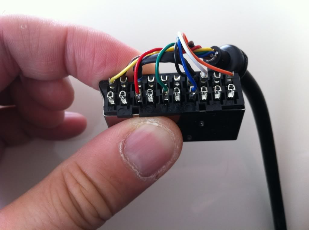
Right, I've got a couple more adapters to make up but for RGB21 this time rather than Euro SCART.
The RGB21 pinout is [
here]
The Euro SCART pinout is [
here]
I'm just a bit unsure what resistor to use between pin 16 (5v) and pin 11 (AV control signal) for the RGB21 lead.
I'm taking pin 11 on RGB21 (AV Control Signal) to be the same as pin 8 (Switch) on Euro SCART.
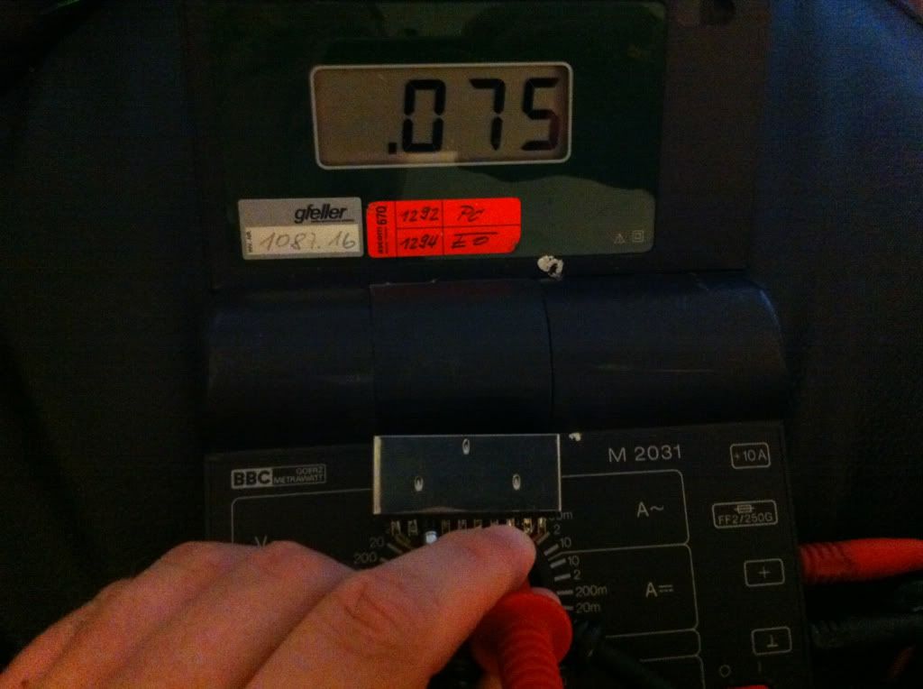
When I made the Euro SCART one for Ralph we found out that the resistance of in the original cable was 75ohms so we used a 75ohm resistor between pins 8 and 16 which worked. However, I seem to be finding different values when looking at RGB21 pinouts and I'm a little unsure of what to use.
The leads are for a XRGB2 and there is a wiki page [
here]. Linked from that page is a another RGB21 pinout:
http://gamesx.com/wiki/doku.php?id=av:japanese_rgb-21"
On that page they show 5v going to pin 11 (AV control signal) and then bridging it to pin 16 with a 3.3k ohm resistor to bring the voltage on pin 16 to 1V.
There is a note saying '*connect to pin 11 via 3.3k Ohm resistor. The resistor isn't usually necessary, and +5v on this pin will most often work.'
Does this mean you can use 5v on both pins with no resistors?
Linked from that page is link to a RGB(21?) > SCART pinout:
http://gamesx.com/wiki/doku.php?id=av:scart2rgb"
It looks like there they are suggesting possibly using a 100ohm resistor on pin 16 (5v line). I presume they are talking about connecting it in series on the 5v line to lower the voltage and not bridging it to 11 (AV control signal). Note there they are connecting it to pin 16 (5v) and not to pin 11.
I've been going round and round in circles and getting more and more confused.

I'm thinking I need to wire 5v to pin 16 but then I'm unsure what resistor I need, if any, between pin 16 (5v) and pin 11 (AV control signal)
With it being used with a XRGB2 rather than a TV I'm wondering if pin 11 needs wiring at all. It would be nice to do it properly though just so the cables would be compatible with a JP RGB21 TV too.